


20040225
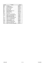
2-7-2
T6700DPL
B568
BT ARM MK12
0VM305728
B569
CAM HOLDER(F) MK12
0VM305722
B570
CAM RACK SPRING(HI) MK11
0VM412923
B571
P.S.W CUT 1.6X4.0X0.5T
0VM408485A
B573
REEL(SP)(D2) MK12
0VM203755
B574
REEL(TU)(D2) MK12
0VM203756
B587
TENSION LEVER ASSEMBLY MK12
0VSA13279
B590
BRAKE ARM(TU) MK12
0VM203752E
B591
BAND BRAKE(TU) MK12
0VM305724C
B592
TG POST MK11
0VM412550
L1051
SCREW, B-TIGHT M2.6X6 PAN HEAD+
GPMB9060
L1053
SCREW, S-TIGHT M2.6X8 WASHER HEAD+
GCMS9080
L1151
SCREW, SEMS M3X4 PAN HEAD + or
CPM33040
SCREW, SEMS M2.6X4 PAN HEAD+
CPM39040
L1191
SCREW, S-TIGHT M2.6X8 WASHER HEAD+
GCMS9080
L1321
SCREW, S-TIGHT M3X6 BIND HEAD+
GBMS3060
L1341
SCREW, P-TIGHT M2X6 PAN HEAD+
GPMP2060
L1406
AC HEAD SCREW MK9
0VM410964
L1450
SCREW, SEMS M2.6X5 PAN HEAD+
CPM39050
L1466
SCREW, S-TIGHT M2.6X6 BIND HEAD+
GBMS9060
L1467
SCREW M2.6X5 WASHER HEAD+
SCM39050
L1474
SCREW, P-TIGHT M2.6X12 WASHER HEAD+
GCMP9120
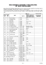
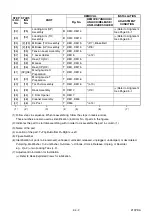
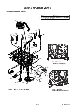
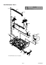
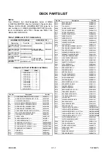
Ref. No.
Description
Part No.
Summary of Contents for TVCR-2104
Page 17: ...1 5 4 T6700DC Fig 4 S 11 S 11 S 11 S 11 Anode Cap 11 CRT CRT CBA...
Page 37: ...Main 2 5 Schematic Diagram 1 8 5 1 8 6 T6700SCM2...
Page 42: ...1 8 15 1 8 16 H V Power Supply 2 2 Schematic Diagram T6700SCP2...
Page 43: ...1 8 17 1 8 18 T6700SCCRT CRT Schematic Diagram...
Page 86: ...2 4 9 Z13PDA Fig DM16 43 41 42 L 13 Fig DM17 44 45 Slide P 9...