1-7-1
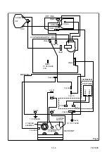
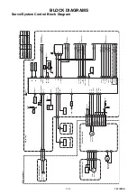
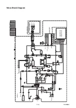
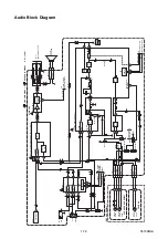
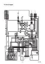
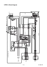
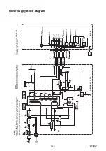
BLOCK DIAGRAMS
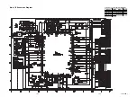
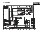
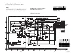
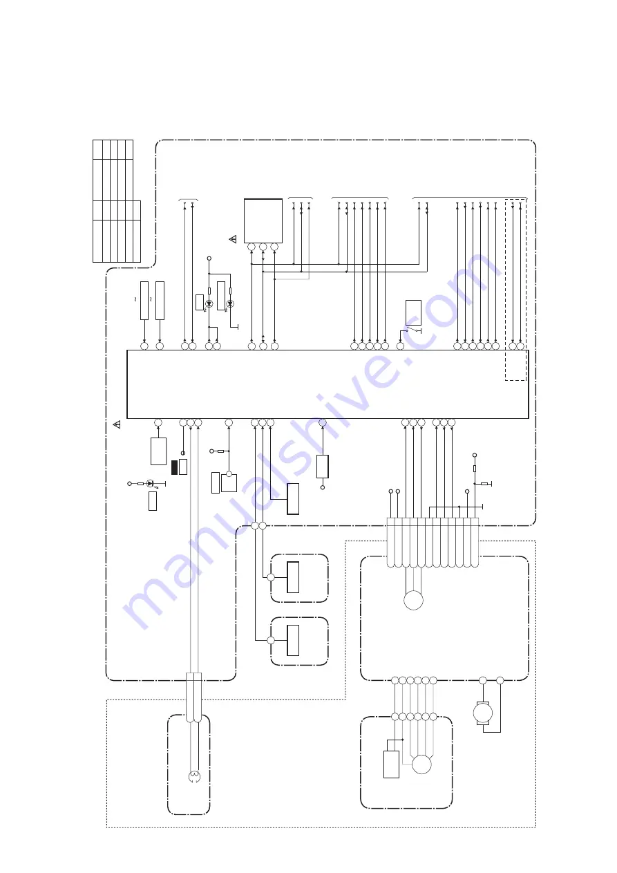
Servo/System Control Block Diagram
T6700BLS
CONTR
OL
HEAD
CL402
AC HEAD ASSEMBLY
MAIN CBA
KEY-2
RF-SW
ST-SENS.
T-REEL
KEY-1
DV-SYNC
C-SYNC
C-SYNC
V-ENV
REMOTE
CTL(+)
RESET
C-ROTA
REC-SAFETY
A-MUTE-H
SCL
SDA
A-MUTE-H
CTL(-)
RF-SW
DV-SYNC
V-ENV
C-ROTA
END-SENS.
IC201
(SERVO/SYSTEM CONTROL)
14
94
95
10
4
80
34
18
15
6
13
74
31
20
72
8
7
RS201
REMO
TE
SENSOR
CTL AMP-OUT
97
AL+5V
D201
S-LED
CTL
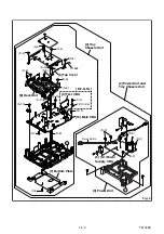
TP001
(DECK
ASSEMBLY
)
END-SENS.
T-REEL
ST-SENS.
Q202
Q205
Q201
Q204
RESET
TIMER+5V
32
33
47
EXT-L
SP-MUTE
SP-MUTE
44
SW211
REC
SAFETY
TO
VIDEO BLOCK
TO
AUDIO BLOCK
KEY SWITCH
KEY SWITCH
SW201 SW205
SCL
(MEMORY)
SDA
6
5
REC-LED
24
REC-LED
23
P-DOWN-L
85
P-ON-H
P-DOWN-L
P-ON-H
67
D202
REC
AL+5V
LD-SW
9
I
2
C-OPEN
45
71
AL+5V
SW212
LD-SW
CS
7
TO POWER
SUPPLY BLOCK
SW206 SW210
SDA
SCL
TO
TV BLOCK
SDA
SCL
IC202
WF3
I
2
C-OPEN
M
M
LOADING
MOTOR
CYLINDER ASSEMBLY
CAPSTAN MOTOR
SENSOR CBA
(ST-SENSOR)
SENSOR CBA
(END-SENSOR)
DRUM
MOTOR
PG
SENSOR
4
C-F/R
1
CM+12V
11
AL+12V(1)
2
P-ON+5V(3)
6
FG-GND
3
C-FG
5
C-CONT
10
M-GND
7
LD-CONT
8
D-CONT
9
D-PFG
12
VG
CN201
C-FG
C-CONT
D-PFG
C-F/R
90
76
87
78
LD-CONT
81
D-CONT
77
CM+12V
AL+12V(1)
P-ON+5V(3)
M
CAPSTAN
MOTOR
D-REC-H
TRICK-H
SECAM-H
SECAM-H
TRICK-H
D-REC-H
SDA
SCL
42
48
29
EXT-L
SCART-H
SCART-MUTE
SCART-H
SCART-MUTE
D204
ST
ANDBY
2
CTL(+)
1
CTL(-)
C,G
+33V
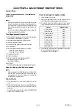
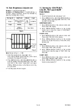
Comparison Char
t of Models & Marks
Model
Mark
TVCR-D2104
TVCR-A2104T
TVCR-A2104TG
D
G
F
Model
Mark
TVCR-A2104
TVCR-B2104
TVCR-C2104
A
B
C
E
TVCR-B2104T
TVCR-C2104T
TVCR-D2104T
H
I
Summary of Contents for TVCR-2104
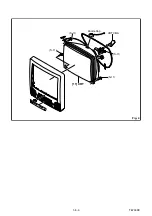
Page 17: ...1 5 4 T6700DC Fig 4 S 11 S 11 S 11 S 11 Anode Cap 11 CRT CRT CBA...
Page 37: ...Main 2 5 Schematic Diagram 1 8 5 1 8 6 T6700SCM2...
Page 42: ...1 8 15 1 8 16 H V Power Supply 2 2 Schematic Diagram T6700SCP2...
Page 43: ...1 8 17 1 8 18 T6700SCCRT CRT Schematic Diagram...
Page 86: ...2 4 9 Z13PDA Fig DM16 43 41 42 L 13 Fig DM17 44 45 Slide P 9...


