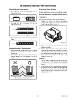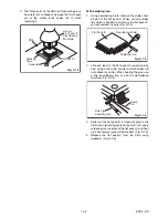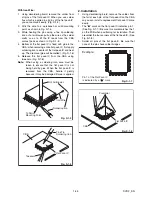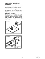
1-7-5
E3TFGDC
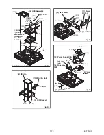
Note:
When removing FFC of Capstan Motor from AV CBA, be sure to replace it with a new FFC.
(Don’t solder FFC which was once removed again.)
[22] AV CBA
[20] DTV Module
CBA Unit
[19] Deck
Assembly
[21] Rear Jack
CBA
FE Head
Cylinder
Assembly
ACE Head
Assembly
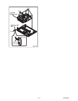
[22] AV CBA
SW507
LD-SW
From
FE Head
BOTTOM VIEW
Lead connections of Deck Assembly and AV CBA
Desolder
FFC of
Capstan
Motor
Printing side
Desolder
Desolder
Desolder
Desolder
From
Cylinder
Assembly
From
ACE Head
Assembly
Lead with
blue stripe
Lead with
white stripe
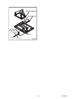
(S-26)
(S-27)
Fig. D8
LD-SW
Pin
Pin
Hole
Hole
Shaft
Cam Gear
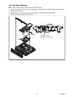
[22] AV CBA
[19] Deck Assembly
Summary of Contents for TD6D-M101
Page 61: ...1 15 3 E3TFGSCAV1 AV 1 10 Schematic Diagram VCR Section...
Page 63: ...1 15 5 E3TFGSCAV3 AV 3 10 Schematic Diagram VCR Section...
Page 64: ...1 15 6 E3TFGSCAV4 AV 4 10 Schematic Diagram VCR Section...
Page 65: ...1 15 7 E3TFGSCAV5 AV 5 10 Schematic Diagram VCR Section...
Page 66: ...1 15 8 E3TFGSCAV6 AV 6 10 Schematic Diagram VCR Section...
Page 67: ...1 15 9 E3TFGSCAV7 AV 7 10 Schematic Diagram VCR Section...
Page 68: ...1 15 10 E3TFGSCAV8 AV 8 10 Schematic Diagram VCR Section...
Page 69: ...1 15 11 E3TFGSCAV9 AV 9 10 Schematic Diagram VCR Section...
Page 70: ...1 15 12 E3TFGSCAV10 AV 10 10 Schematic Diagram VCR Section...
Page 73: ...1 15 15 Rear Jack Schematic Diagram VCR Section E3TFGSCRJ...
Page 79: ...1 15 21 E3TFGSCD6 DVD HDD Main 6 7 Schematic Diagram DVD HDD Section...
Page 81: ...1 15 23 E3TFGSCDTV DTV Module Schematic Diagram DVD HDD Section...
Page 82: ...1 15 24 E3TFGSCSATA SATA Schematic Diagram...
Page 107: ...TD6D M101 E3TFGEH 2013 04 22...

