1-7-3
E3TFGDC
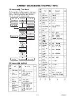
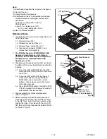
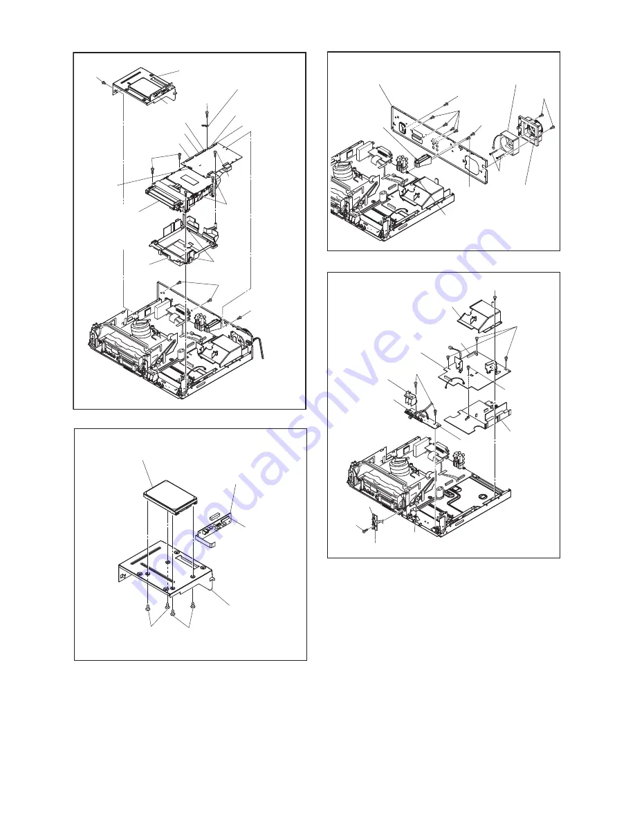
(S-10)
(S-9)
CN101
CN901
CN701
CN981
Mecha Earth
Plate
CN652
CN502
(S-11)
(S-7)
(S-6)
CN5002
* See Reference Note 2.
Dust
Cover
Hook
[6] HDD Assembly
[5] *DVD
Mechanism
& DVD/HDD
Main CBA
Assembly
(S-7)
(S-8)
Fig. D3
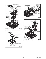
(S-12)
(S-12)
CN5003
[9] HDD Bracket
[8] HDD Unit
[7] SATA CBA Unit
Fig. D4
(S-13)
(S-17)
(S-16)
(S-17)
(S-15)
(S-14)
[11] Motor
DC Fan
[10] Fan Holder
[12] Rear Panel
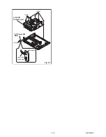
CN1002
Rear Holder
Fig. D5
FFC Guide
Mode Lens
Holder
CL1001
CN3605
(S-21)
(S-22)
(S-18)
(S-19)
(S-20)
[13] Power Supply CBA
[14] Power
Holder
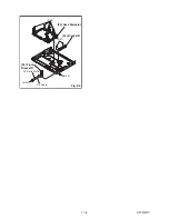
[16] Function
CBA
[15] SW CBA
Desolder
CN1504
Fig. D6
Summary of Contents for TD6D-M101
Page 61: ...1 15 3 E3TFGSCAV1 AV 1 10 Schematic Diagram VCR Section...
Page 63: ...1 15 5 E3TFGSCAV3 AV 3 10 Schematic Diagram VCR Section...
Page 64: ...1 15 6 E3TFGSCAV4 AV 4 10 Schematic Diagram VCR Section...
Page 65: ...1 15 7 E3TFGSCAV5 AV 5 10 Schematic Diagram VCR Section...
Page 66: ...1 15 8 E3TFGSCAV6 AV 6 10 Schematic Diagram VCR Section...
Page 67: ...1 15 9 E3TFGSCAV7 AV 7 10 Schematic Diagram VCR Section...
Page 68: ...1 15 10 E3TFGSCAV8 AV 8 10 Schematic Diagram VCR Section...
Page 69: ...1 15 11 E3TFGSCAV9 AV 9 10 Schematic Diagram VCR Section...
Page 70: ...1 15 12 E3TFGSCAV10 AV 10 10 Schematic Diagram VCR Section...
Page 73: ...1 15 15 Rear Jack Schematic Diagram VCR Section E3TFGSCRJ...
Page 79: ...1 15 21 E3TFGSCD6 DVD HDD Main 6 7 Schematic Diagram DVD HDD Section...
Page 81: ...1 15 23 E3TFGSCDTV DTV Module Schematic Diagram DVD HDD Section...
Page 82: ...1 15 24 E3TFGSCSATA SATA Schematic Diagram...
Page 107: ...TD6D M101 E3TFGEH 2013 04 22...


