
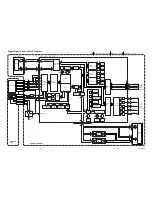


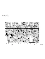


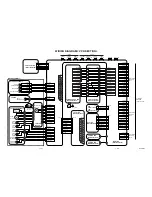

Power Supply & Junction Schematic Diagram < VCR Section >
1-10-21
1-10-22
H9512SCP
NOTE :
The voltage for parts in hot circuit is measured using
hot GND as a common terminal.
CAUTION !
For continued protection against fire hazard,
replace only with the same type fuse.
CAUTION !
Fixed voltage ( or Auto voltage selectable ) power supply circuit is used in this unit.
If Main Fuse (F1001) is blown, check to see that all components in the power supply
circuit are not defective before you connect the AC plug to the AC power supply.
Otherwise it may cause some components in the power supply circuit to fail.
Summary of Contents for DCVR-4800
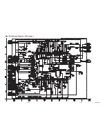
Page 29: ...Main 1 9 Schematic Diagram VCR Section 1 10 3 1 10 4 H9512SCM1...
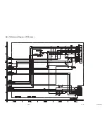
Page 31: ...1 10 7 1 10 8 H9512SCM3 Main 3 9 Schematic Diagram VCR Section...
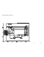
Page 32: ...Main 4 9 Schematic Diagram VCR Section 1 10 9 1 10 10 H9512SCM4...
Page 33: ...Main 5 9 Schematic Diagram VCR Section 1 10 11 1 10 12 H9512SCM5...
Page 34: ...Main 6 9 Schematic Diagram VCR Section 1 10 13 1 10 14 H9512SCM6...
Page 35: ...Main 7 9 Schematic Diagram VCR Section 1 10 15 1 10 16 H9512SCM7...
Page 36: ...Main 8 9 DVD Open Close Schematic Diagram VCR Section 1 10 17 1 10 18 H9512SCM8...
Page 37: ...1 10 19 1 10 20 Main 9 9 Schematic Diagram VCR Section H9512SCM9...
Page 39: ...1 10 23 1 10 24 Jack Schematic Diagram VCR Section H9512SCJ...
Page 40: ...1 10 25 1 10 26 Function Schematic Diagram VCR Section H9512SCF...
Page 41: ...1 10 27 1 10 28 AFV Schematic Diagram VCR Section H9512SCAFV...
Page 43: ...1 10 31 Main CBA Bottom View BH9510F01012A 1 10 32...
Page 47: ...DVD Main 1 3 Schematic Diagram DVD Section H9512SCD1 1 10 39 1 10 40...
Page 48: ...1 10 41 1 10 42 DVD Main 2 3 Schematic Diagram DVD Section H9512SCD2...
Page 50: ...DVD Main 3 3 Schematic Diagram DVD Section 1 10 45 1 10 46 H9512SCD3...
Page 97: ...DCVR 4800 H9512FD...


