


1-5-1
H9500PFS
PREPARATION FOR SERVICING
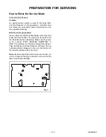
How to Enter the Service Mode
AAbout Optical Sensors
Caution:
An optical sensor system is used for the Tape Start
and End Sensors on this equipment. Carefully read
and follow the instructions below. Otherwise the unit
may operate erratically.
What to do for preparation
Insert a tape into the Deck Mechanism Assembly and
press the PLAY button. The tape will be loaded into
the Deck Mechanism Assembly. Make sure the power
is on, connect TP501 (SENSOR INHIBITION) to
GND. This will stop the function of Tape Start Sensor,
Tape End Sensor and Reel Sensors. (If these TPs are
connected before plugging in the unit, the function of
the sensors will stay valid.) See Fig. 1.
Note: Because the Tape End Sensors are inactive, do
not run a tape all the way to the start or the end of the
tape to avoid tape damage.
TP501
S-INH
Q504
Q503
Fig. 1
Summary of Contents for DCVR-4800
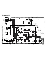
Page 29: ...Main 1 9 Schematic Diagram VCR Section 1 10 3 1 10 4 H9512SCM1...
Page 31: ...1 10 7 1 10 8 H9512SCM3 Main 3 9 Schematic Diagram VCR Section...
Page 32: ...Main 4 9 Schematic Diagram VCR Section 1 10 9 1 10 10 H9512SCM4...
Page 33: ...Main 5 9 Schematic Diagram VCR Section 1 10 11 1 10 12 H9512SCM5...
Page 34: ...Main 6 9 Schematic Diagram VCR Section 1 10 13 1 10 14 H9512SCM6...
Page 35: ...Main 7 9 Schematic Diagram VCR Section 1 10 15 1 10 16 H9512SCM7...
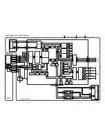
Page 36: ...Main 8 9 DVD Open Close Schematic Diagram VCR Section 1 10 17 1 10 18 H9512SCM8...
Page 37: ...1 10 19 1 10 20 Main 9 9 Schematic Diagram VCR Section H9512SCM9...
Page 39: ...1 10 23 1 10 24 Jack Schematic Diagram VCR Section H9512SCJ...
Page 40: ...1 10 25 1 10 26 Function Schematic Diagram VCR Section H9512SCF...
Page 41: ...1 10 27 1 10 28 AFV Schematic Diagram VCR Section H9512SCAFV...
Page 43: ...1 10 31 Main CBA Bottom View BH9510F01012A 1 10 32...
Page 47: ...DVD Main 1 3 Schematic Diagram DVD Section H9512SCD1 1 10 39 1 10 40...
Page 48: ...1 10 41 1 10 42 DVD Main 2 3 Schematic Diagram DVD Section H9512SCD2...
Page 50: ...DVD Main 3 3 Schematic Diagram DVD Section 1 10 45 1 10 46 H9512SCD3...
Page 97: ...DCVR 4800 H9512FD...


