User’s Manual for FD556 Digital 2-Phase Stepper Driver
User’s Manual for FD556 Digital 2-Phase Stepper Driver
5 6
3.
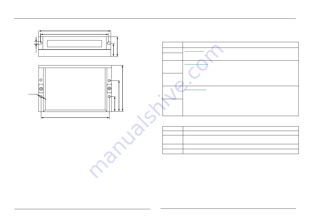
Mechanical Dimensions (unit: mm, 1 inch = 25.4 mm)
Figure 1: Mechanical dimensions
*
Recommended to use side mounting for better heat dissipation, When designing
the installation size, pay attention to the terminal size and wiring.
4. Elimination of Heat
1
)
Driver’s reliable working temperature should be <60
℃
, and motor working
temperature should be <80
℃
(176
℉
);
2
)
It is recommended to use automatic idle-current mode, namely current
automatically reduce to 50% when motor stops, so as to reduce driver heating and
motor heating;
3
)
It is recommended to mount the driver vertically to maximize heat sink area. Use
forced cooling method to cool the system if necessary, Ensure that the drives
operation in a reliable operating temperature range.
Ⅲ
.Pin Assignment and Description
1. Interface description
1
)
Control Signal Connector
Signal
Functions Details
PUL+
Pulse signal: This input represents pulse signal, each rising edge active,
4.5~28Vdc when PUL-HIGH, 0~0.5V when PUL-LOW, For reliable
response, pulse width should be longer than 1.5μs.
PUL-
DIR+
Direction signal: this signal has low/high voltage levels, representing two
directions of motor rotation; For reliable motion response, DIR signal
should be ahead of PUL signal by 2μs at least. 4.5V-28Vdc when
DIR-HIGH, 0-0.5V when DIR-LOW. Please note that rotation direction is
also related to motor-driver wiring match. Exchanging the connection of
two wires for a coil to the driver will reverse motion direction.
DIR-
ENA+
Enable signal: This signal is used for enabling/disabling the driver. High
level for enabling the driver and low level for disabling the driver. When
ENA-HIGH is connected to 4.5V-28Vdc, ENA-LOW is connected to
0-0.5V (or Internal optical coupling is conducted), the driver will cut off
the current of each phase of the motor to make the motor in a free state,
step pulses are not responded at this time. Usually left
unconnected
(enabled)
.
ENA-
2
)
Power Connector Configurations
Signal
Functions Details
GND
Power Ground.
+Vdc
Power supply, +24V~ +50Vdc Including voltage fluctuation and EMF
voltage, Recommended 36Vdc supply.
A+
、
A-
Motor coil A (leads A+ and A-)
B+
、
B-
Motor coil B (leads B+ and B-)
3
)
RS232/RS485 Communication Port
Special RS232 cable (Prohibition of charging plug) designed to setup communication
between the drive and PC-based configuration & tuning software ProTuner. The PC
software is used to configure the peak current, microstep, active level, current loop
parameters and the driver function, and so on.
118
112
34
112
22.
5
4.
5
4-
Ф
3.5
75.
5
25.
3
47.
8


