


3-9-8 Lead Lag Setting
CAUTION
This is a simple function to keep the fixed room temperature with
multiple indoor units. If you need a precise temperature control,
such as maintaining a server room, take other appropriate mea-
sures. Even if information devices or data are damaged by using
this function, we do not compensate them.
When enabling the Lead lag operation, the indoor units in the
RC Group take turns stopping 1 or 2 at a time.
NOTES
• Make sure to connect the indoor units to the power sup-
ply at midnight (12:00 AM). The indoor units switch the
operation/stop at this time.
• When using Lead lag operation, disable the Human sen-
sor. If it is enabled, the air conditioners may stop in the
absence and the room temperature may rise. (Refer to
[3-6-5 Human Sensor Setting]”.)
[Check before the setting]
Preparation for Lead lag operation
Make sure to meet all the following conditions. Otherwise,
[Lead Lag setting] does not appear on the remote controller
display.
Condition
Reference for setting
Connect 2 or more indoor
units.
Consult authorized service
personnel.
Do not connect other remote
controller or converter.
Consult authorized service
personnel.
Set this unit to the primary
remote controller.
Consult authorized service
personnel.
Activate the Auto restart
function of the indoor unit.
Refer to the operation manual
of the indoor unit.
Activate the remote control-
ler sensor.
Refer to "3-9-5 RC Sensor
Setting".
When enabling the Lead lag operation, the following func-
tions or settings are deactivated.
- Timer settings
- Set temp. auto return setting
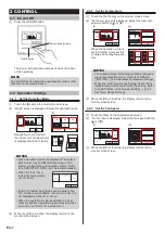
Setting procedure
(1) Touch the [Lead Lag Setting]
on the “Initial Setting” screen.
“Lead Lag Setting” screen is
shown.
Back
Previous
Page
Page 3/ 3
Initial Setting
R.C. Master/
Slave Setting
Lead Lag
Setting
I.U. Display
Number Setting
(2) The screen has 2 pages which are switched by touching
the [Next page] or [Previous Page].
Enable/Disable
[Enable]
[7 Day]
[10min.]
Cycle
Over Lap Time
Lead Lag Setting
Page 1/ 2
Next
Page
Back
Backup Units
[2/16]
[Enable]
Lag Operation
Lead Lag Setting
Page 2/ 2
Back
Previous
Page
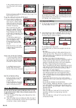
Cycle setting
(3) Touch the [Cycle] on the “Lead Lag” screen.
(4) “Cycle” screen is shown. Set the term by touching [ ] or
[ ]. You can set the term “TEST” or from 1 day to 7
days in 1-day increments.
(3)
(4)
Enable/Disable
[Enable]
[7 Day]
[10min.]
Cycle
Over Lap Time
Lead Lag Setting
Page 1/ 2
Next
Page
Back
7
Cycle
Cancel
OK
Day
When touching [OK], the display returns to the “Lead
Lag” screen.
NOTES
• Each time the set term passes, the indoor units
switch the operation/stop following the Lead lag
setting.
• When setting “TEST” and enabling the Lead lag op-
eration, the indoor units switch the operation/stop
each time you press the [On/Off] button.
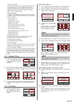
Overlap time setting
(5) Touch the [Over Lap Time] on the “Lead Lag” screen.
(6) “Over Lap Time” screen is displayed. Set the overlap
time by touching [ ] or [ ]. The overlap time can be set
“None” or from 10 minutes to 30 minutes in 10 minutes
increments.
When selecting “None”, the Lead lag operation has no
overlap time.
(5)
(6)
Enable/Disable
[Enable]
[7 Day]
[10min.]
Cycle
Over Lap Time
Lead Lag Setting
Page 1/ 2
Next
Page
Back
10
Over Lap Time
Cancel
OK
min.
When the [OK] is touched, the display returns to the “Lead
Lag” screen.
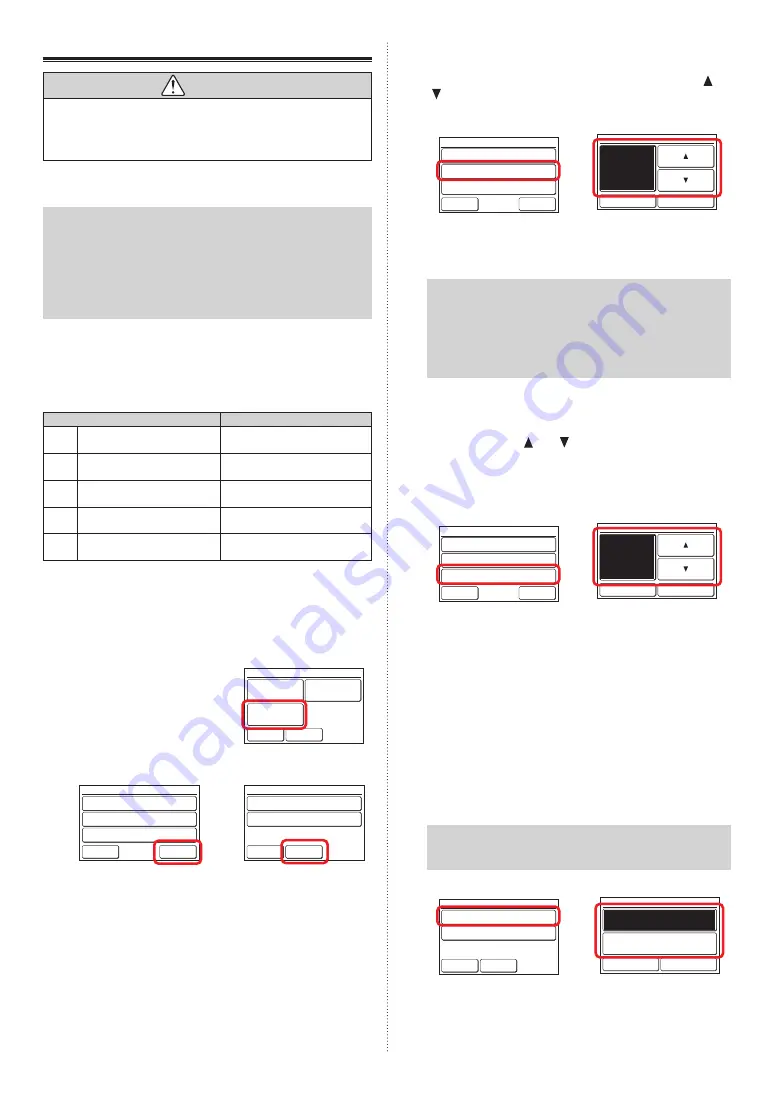
Backup Units setting
Select the number of indoor units which stop simultaneously.
The current setting is shown on the right side of [Backup
Units].
The denominator means the number of the connected indoor
units and the numerator means the number of the stopped
indoor unit simultaneously.
(7) Touch the [Backup Units] on the “Lead Lag” screen.
(8) “Backup Units” screen is displayed. Touch the [2 Units]
or [1 Unit].
NOTE
If 2 indoor units are connected, the setting is fixed to
“1 Unit”.
(7)
(8)
Backup Units
[2/16]
[Enable]
Lag Operation
Lead Lag Setting
Page 2/ 2
Back
Previous
Page
Backup Units
Cancel
OK
2 Units
1 Unit
When touching [OK], the display returns to the “Lead Lag”
screen.
En-21
Summary of Contents for UTY-RNRGZ5
Page 27: ......


