Fujitsu UTY-RNRGZ1 Operating Manual Download Page 6

1 MONITOR

1-1  Monitor

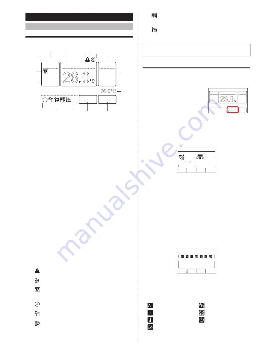
1-1-1  Monitor mode screen

Monitor mode screen is the home screen of this unit.

26.0

°C

Cool

Auto

Office

Set Temp.

26.0°C

Mode

Menu

Status

Fan

Fri 10:00AM

Room Temp.

(i)

(c)

(e)

(f)

(d)

(a)

(i)

(i)

(g)

(h)

(b)

(a)  R.C. group name:  

Name of the remote controller group to which this unit is 

connected. Refer to [3 Setting] → [3-8 Initial Setting] → 

[3-8-4 R.C.Group Name Setting].

(b)  Clock: 

Refer to [3 SETTING] → [3-8 Initial Setting] → [3-8-2 

Date Setting].

(c)  Mode: 

When this is touched, the display switches to the “Mode” 

screen. Refer to [2 CONTROL] → [2-2 Operation Set-

tings] → [2-2-1 Set the Operation Mode].

(d)  Set temp.: 

When this is touched, the display switches to the tem-

perature setting screen. Refer to [2 CONTROL] → [2-2 

Operation Settings] → [2-2-2 Set the Temperature].

(e)  Fan:  

When this is touched, the display switches to the fan 

speed setting screen. Refer to [2 CONTROL] → [2-2 

Operation Settings] → [2-2-3 Set the Fan Speed].

(f)  Room temp.: 

The ambient temperature sensed by this unit is dis-

played. Refer to [3 SETTING] → [3-8 Initial Setting] → 

[3-8-7 Display Item Setting].

(g)  Menu: 

When this is touched, the display switches to the “Menu” 

screen. Refer to [3 SETTING].

(h)  Status:  

When this is touched, the display switches to the “Status” 

screen. Refer to [1-1-2 Status display].

(i)  Status icons:

An error occurred. Refer to [1-1-2 Status display] → 

< Error Information screen >.
Operation from this unit is prohibited by the Central 

Controller. Refer to [1-1-2 Status display].
Mode mismatch. The mode which cannot operate 

simultaneously is selected. Refer to [1-1-2 Status 

display].
The On Timer, Off Timer, or Auto Off Timer is set. 

Refer to [3 SETTING] → [3-3 Timer Setting].
The weekly timer is set. Refer to [3 SETTING] → 

[3-4 Weekly Timer Setting].
The set temperature automatic return setting is set. 

Refer to [3 SETTING] → [3-5 Special Setting] → 

[3-5-2 Set Temp. Auto Return].

It shows that it is time to clean the filter. Refer to 

[3 SETTING] → [3-9 Maintenance] → [3-9-3 Filter 

Sign Reset].
The temperature sensor of this unit is used. Refer 

to [3 SETTING] → [3-8 Initial Setting] → [3-8-5 R.C. 

Sensor Setting].

For the screen display other than Chinese, this product uses 

a Bitmap font made and developed by Ricoh Company, Ltd.

1-1-2  Status display

The remote controller and indoor unit setting status are dis-

played.

Touch the [Status] on monitor 

mode screen. “Status” screen is 

displayed.

26.0

°C

Cool

Auto

Set Temp.

Mode

Menu

Status

Fan

Fri 10:00AM

The “Status” screen has 2, 3 or 4 pages which are switched 

by touching the [Next Page] or [Previous Page]. When the 

[Monitor] is touched, the display returns to the monitor mode 

screen. 

(*: Items that indoor unit does not support are not displayed.)

< Page 1 >

Status

Air Flow Direction

VT

Off

1

3

Off

HZ

Economy

Individual

Anti Freeze

Page  1/  4

Monitor

Next

Page

•  Air Flow Direction*: 

The air flow direction setting is displayed. The setting will 

appear only for indoor units which can set air flow direc-

tions. 

“Individual” is displayed only when this remote control-

ler is connected to the indoor unit which supports the 

appropriate function. When setting is performed, [

] is 

displayed.


Refer to [3 Setting]→[3-2 Air Flow Direction 

Setting]→[3-2-3 Individual VT Hold].

•  Economy: 

ON or OFF of the economy setting is displayed.

•  Anti Freeze*: 

ON or OFF of the anti freeze setting is displayed.

< Page 2 >

• Under Maintenance

• Forced Stop

• Mode Mismatch

Previous

Page

Status

R.C. Prohibition

Special State

Page  2/  4

Monitor

Next

Page

•  R.C. Prohibition: 

The functions whose operation from this unit and Wireless 

type remote controller is prohibited by the Central Control-

ler are displayed by icons. The contents of each icon are 

as follows:

:All operations

:On and Off

:On

:Mode setting

:Temperature setting

:Timer setting

:Filter sign reset

En-5

En-6

Summary of Contents for UTY-RNRGZ1

Page 1: ...osibles consultas futuras MANUALE DI ISTRUZIONI UNITÀ DI CONTROLLO A FILO Conservare questo manuale per consultazione futura ΕΓΧΕΙΡΙΔΙΟ ΛΕΙΤΟΥΡΓΙΑΣ ΕΝΣΥΡΜΑΤΟ ΤΗΛΕΧΕΙΡΙΣΤΗΡΙΟ Διατηρήστε το παρόν εγχειρίδιο για μελλοντική αναφορά MANUAL DE FUNCIONAMENTO CONTROLO REMOTO COM FIOS Guarde este manual para consulta futura РУКОВОДСТВО ПО ЭКСПЛУАТАЦИИ ПРОВОДНОЙ ПУЛЬТ ДИСТАНЦИОННОГО УПРАВЛЕНИЯ Сохраните дан...

Page 2: ...LINE 3 1 Terminology 3 2 Password configuration 4 3 Name of parts 4 1 MONITOR 1 1 Monitor 5 1 1 1 Monitor mode screen 5 1 1 2 Status display 5 1 1 3 Child Lock 6 1 1 4 Emergency Stop 6 2 CONTROL 2 1 On and Off 7 2 2 Operation Settings 7 2 2 1 Set the Operation Mode 7 2 2 2 Set the Temperature 7 2 2 3 Set the Fan Speed 7 3 SETTING 3 1 Select the Setting Items 8 3 2 Air Flow Direction Setting 8 3 2 ...

Page 3: ...k Next Page Page 2 3 Maintenance Test Run R C Address Setting Function Setting I U Address Verification Back Previous Page Page 3 3 Maintenance Initialization Installer Password Change Summer Time Setting Cancel OK Enable Disable Back Preference Panel Calibration Backlight Setting Contrast Back Special Setting Set Temp Range Setting Set Temp Auto Return Anti Freeze Economy Next Page Page 1 2 Back ...

Page 4: ...will cause injury trouble or electric shock Do not insert articles into the slit parts of this unit Doing so will cause trouble heating or electric shock SYSTEM OUTLINE 1 Terminology System related terms is for VRF system a VRF system VRF Variable Refrigerant Flow is a large multi system that effectively air conditions a wide variety of spaces from large buildings to personal residences b Other sy...

Page 5: ...r a description of backlight setting refer to 3 SETTING 3 7 Preference 3 7 2 Backlight Set ting Lightly touch the touch panel with your finger tips A commercially available stylus pen can also be used If pushed with too much force or operated with a rod pencil or ballpoint pen etc the display may be scratched or damaged Do not touch 2 or more places simultaneously Correct operation cannot be perfo...

Page 6: ...Refer to 3 SETTING 3 5 Special Setting 3 5 2 Set Temp Auto Return It shows that it is time to clean the filter Refer to 3 SETTING 3 9 Maintenance 3 9 3 Filter Sign Reset The temperature sensor of this unit is used Refer to 3 SETTING 3 8 Initial Setting 3 8 5 R C Sensor Setting For the screen display other than Chinese this product uses a Bitmap font made and developed by Ricoh Company Ltd 1 1 2 St...

Page 7: ...r operating indoor unit can be selected Refer to 4 OPERATION TIPS for the modes which can be oper ated simultaneously Set Temp Limited Indoor unit temperature setting is limited by the Central controller Energy Saving Operation The energy saving is set by the Energy Manager for Sys tem Controller Defrost At heating operation the outdoor unit performs Defrost operation The indoor unit fan is stoppe...

Page 8: ... Slave Indoor Unit When the operation mode is switched in a heat recovery system operation preparations may take some time but this is not a malfunction 3 When the OK is touched the display returns to the monitor mode screen 2 2 2 Set the Temperature 1 Touch the Set Temp on the monitor mode screen 2 Set Temp screen is displayed Adjust the room tem perature with the or 1 2 26 0 C Cool Auto Set Temp...

Page 9: ...r Flow Direction 1 Touch the VT Setting on the Air Flow Direction Set ting screen 2 VT Air Flow Direction Setting screen is displayed Touch or and set the air flow direction or Swing 1 2 1 3 Air Flow Direction Setting Back VT HZ Setting Setting 1 1 4 VT Air Flow Direction Setting Cancel OK 3 When the OK is touched after setting the data is transmitted to the indoor unit and the display returns to ...

Page 10: ...complete or canceled the display returns to this screen When Back is touched the display returns to the Main Menu screen 3 3 1 On Timer 1 Touch the On Timer on the Timer Setting screen When the Password Verification screen is displayed enter the password and touch OK Back On Timer Disable Disable Disable Off Timer Auto Off Timer Timer Setting Enable the On Timer 2 On Timer screen is displayed Touc...

Page 11: ... the Manual Operation Operation Stop Time Cancel OK In min 30 Fri 10 00AM When the OK is touched the display returns to the Auto Off Timer screen Set the time range of Auto Off Timer 6 Touch the Time Range Setting on the Auto Off Timer screen 7 Time Range Setting screen is displayed Touch the Time Range 6 7 Enable Disable Enable In 30 min Operation Stop Time Time Range Setting Auto Off Timer Fri 1...

Page 12: ...d after a setting change screen is displayed the display returns to the Weekly Timer Setting screen Note To disable use of a schedule already set touch None at screen of 2 3 4 2 Schedule Setting Select the schedule to be set 1 Touch the Schedule Setting on the Weekly Timer Set ting screen 2 Schedule Setting screen is displayed When the Schedule 1 or Schedule 2 is touched each setting screen is dis...

Page 13: ...M Sun 08 00AM On Dry Mon Wed Thu Fri Sat Tue 28 0 c 10 00AM Cool 26 0 c 12 00PM 24 0 c 03 00PM Off c Next touch the day of the week to be pasted When the Paste is touched a dotted bar is displayed over the day of the week to be pasted Con tinue to paste to other days of the week 1 2 3 c c c Cancel Copied Pasted Paste OK Schedule 1 Setting Fri 10 00AM Sun Mon Wed Thu Fri Sat Tue To cancel the paste...

Page 14: ...it operation stops Fan Control for Energy Saving for administrator When the set temperature is reached during cooling operation the fan operates intermittently and power is saved When the item to be set is touched the display switches to each setting screen When each setting is complete or canceled the display returns to this screen When Back is touched the display returns to the Main Menu screen ...

Page 15: ... ting screen Note The settable upper limit value and lower limit value may be different depending on the indoor unit model and set ting at installation Apply the setting 7 Touch the OK on the Set Temp Range Setting screen After the setting change screen is displayed the display returns to the Special Setting screen 18 0 c 18 0 c 26 0 c 30 0 c 24 0 c 30 0 c Enable Disable Enable Set Temp Range Sett...

Page 16: ...een When the Back on the Human Sensor Setting is touched the display returns to the Special Setting screen 3 5 6 Fan Control for Energy Saving for administrator 1 Touch the Fan Control for Energy Saving on the Spe cial Setting screen When the Password Verification screen is displayed enter the password and touch the OK 2 Fan Control for Energy Saving screen is displayed Touch the Enable on the Fan...

Page 17: ... press the Retry button 3 7 2 Backlight Setting 1 Touch the Backlight Setting on the Preference screen Back Preference Panel Calibration Backlight Setting Contrast Enable or disable the backlight 2 Backlight Setting screen is displayed Touch the En able Disable on the Backlight Setting screen 3 Enable Disable screen is displayed Select the Enable or Disable 2 3 Enable Disable Enable 30s 2 Automati...

Page 18: ...eset Temp Unit Setting The temperature display unit is switched to C or F Factory settings is C R C Group Name Setting The remote controller group name can be set or changed RC Sensor Setting This setting uses the sensor of this unit to sense the room temperature The room temperature can be sensed at a position closer to the person than the indoor unit sensor Factory settings is Not Used Master In...

Page 19: ... screen is displayed Touch the Date Format 8 9 Date Setting Date and Time Setting Display Format Setting Back Display Format Setting Cancel OK Fri 10 00AM Date Format Time Format Day Month Year 12 00 11 59AM PM 10 Date Format screen is displayed Select the desired format When the OK is touched after a setting change screen is displayed the display returns to the Display Format Setting screen 11 To...

Page 20: ...to the Initial Set ting screen 3 8 6 Password Setting 1 Touch the Password Setting on the Initial Setting screen Back Previous Page Page 2 3 Initial Setting R C Sensor Setting Password Setting Display Item Setting Master Indoor Unit Setting Next Page Change the Password 2 Password Setting screen is displayed Touch the Change Password 3 Password Verification screen is displayed Enter the current pa...

Page 21: ...tting is complete touch the OK on the Display Item Setting screen After the setting change screen is displayed the display returns to the Initial Setting screen Filter Sign Visible Display Item Setting Cancel OK Room Temp Visible 3 9 Maintenance for administrator Verification operation and setting for administrator informa tion are performed 1 Touch the Maintenance on the Main Menu screen 2 When P...

Page 22: ...d The screen has 5 pages which are switched by touching the Next Page or Previous Page Items that indoor unit does not support are not dis played On Timer Operation Start Time Off Timer Operation Stop Time Auto Off Timer Operation Stop Time Time Range Disable 0 5hr Disable 0 5hr Disable 30min Back Next Page Page 1 5 Setting Status List Weekly Timer Set Temp Auto Return Cool Heat Disable Disable 60...

Page 23: ...ool Dry Auto Heat Fan Heating priority is set by external input Heat Auto Cool Dry Fan 4 1 4 Heat pump system a Refer to the following table Status Selectable Not selectable Other indoor unit is in cool ing operation Cool Dry Auto Heat Fan Other indoor unit is in dehu midifying operation Cool Dry Auto Heat Fan Other indoor unit is in heat ing operation Heat Auto Cool Dry Fan Other indoor unit is i...

Page 24: ...n Dimensions H W D mm in 120 120 20 4 4 3 4 4 3 4 13 16 Weight g oz 220 7 76 5 3 Error Code For the details of the indoor unit or outdoor unit error when checking the error contents refer to the error codes in each installation manual Error code Contents CC 1 Sensor error C2 1 Transmission PCB error 12 1 Wired remote controller communication error 12 3 Number excess of device in wired remote contr...

Page 25: ......

Reviews: