SK-91465X-100PMC User Guide
Chapter 3 Jumpers and Switches
UG-910056-11
- 18 -
© Fujitsu Microelectronics Europe GmbH
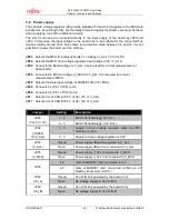
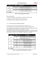
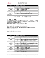
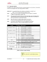
Jumper
Setting
Description
Closed
LIN-transceiver is enabled
JP37
(LIN A enable)
Open
LIN-transceiver is disabled
Closed
LIN Master-mode
JP32
(LIN A Master)
Open
LIN Slave-mode
Closed
Vs of LIN B is powered by the board
JP38
(VBAT_A)
Open
No voltage supply to Vs of LIN B
Default: grey
Table 3-6: UART “B”/ LIN “A” jumper settings
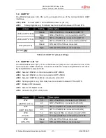
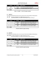
3.6 UART ”C” / LIN “B”
One RS232-transceiver (U10) or one LIN-transceiver (U8) can be connected to one of the
microcontroller’s UART interfaces. Connect to D-Sub X12 corresponding RS232 or LIN
cable. By default RS232 is selected to X12.
JP67 Selects if RS232 or LIN is connected to SIN6 of MCU
JP68 Selects if RS232 or LIN is connected to SOT6 of MCU
JP65 Selects if UARTC or LINB is connected to pin2 of X12
JP69 Some programs (e.g. Terminals) need a connection between CTS and RTS
JP57 Enable LIN-Transceiver
JP54 Selects LIN Master mode
JP60 Connects Vs (Pin 1 of X12) to Vin
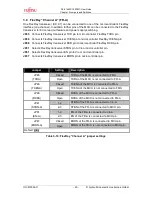
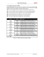
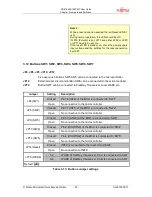
Jumper
Setting
Description
1-2
SIN6 of the MCU is connected to U10 (RS232)
JP67
(UART C / LIN B)
2-3
SIN6 of the MCU is connected to U8 (LIN)
1-2
SOT6 of the MCU is connected to U10 (RS232)
JP68
(UART C / LIN B)
2-3
SOT6 of the MCU is connected to U8 (LIN)
1-2
BUS Signal (LINB) is connected to pin2 of X12
JP65
(X12 pin2)
2-3
Tx Signal (UARTC) is connected to pin2 of X12
Closed
RTS and CTS of X12 are connected
JP69
(RTS-CTS)
Open
RTS and CTS of X12 are not connected
Closed
LIN-transceiver is enabled
JP57
(LIN B enable)
Open
LIN-transceiver is disabled
Closed
LIN Master-mode
JP54
(LIN B Master)
Open
LIN Slave-mode

