background image

38

Service Supplement

 TX150 

S5

Replacing the system board

Replacement routines

4.11

Replacing the system board

I

There are two versions:

SAS version: S26361-D2399-A*; additionally equipped with a SAS 
controller and the SAS connectors SAS MLC1 and SAS MLC1

SATA version: S26361-D2399-B*

Ê

Open the server as described in the 

section “Preparation” on page 17

.

Ê

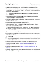
Lay the server on a table with the uncovered side facing upward. Place the 
server in such a way that the feet can project over the edge.

Ê

Remove all external cables.

Ê

Remove all controllers from their slots (for a description see the Operating 
Manual and the Options Guide). Take note of the slots of the controllers and 
the cabling.

Ê

Remove the system fan (see the 

section “Replacing the system fan” on 

page 22

).

Ê

Remove the processor (see the 

section “Replacing the processor” on 

page 32

).

Ê

Remove the memory modules (for a description see the Options Guide).

Ê

Remove all cables which may be connected to the system board.

Summary of Contents for PRIMERGY TX150 S5

Page 1: ...0 S5 Server Service Supplement Susanne Däschlein Fujitsu Siemens Computers GmbH München 81730 München e mail email manuals fujitsu siemens com Tel 089 61001155 Fax 49 700 372 00000 TX150 S5 Sprachen En Edition September 2006 ...

Page 2: ...according to DIN EN ISO 9001 2000 To ensure a consistently high quality standard and user friendliness this documentation was created to meet the regulations of a quality management system which complies with the requirements of the standard DIN EN ISO 9001 2000 cognitas Gesellschaft für Technik Dokumentation mbH www cognitas de Copyright and Trademarks Copyright 2006 Fujitsu Siemens Computers Gmb...

Page 3: ... 18 4 1 2 2 Removing the rack front cover 19 4 2 Replacing the operating panel module 19 4 3 Replacing the DVD DVD RW drive 20 4 4 Replacing the system fan 22 4 5 Replacing the standard PS 24 4 6 Replacing the Power backplane 26 4 7 Replacing the SAS SATA backplane 27 4 8 Replacing the IDTEMP combo 29 4 9 Replacing the intrusion switches 30 4 10 Replacing the processor 32 4 11 Replacing the system...

Page 4: ......

Page 5: ...t groups This Service Supplement completes the information given in the Operating Manual the Options Guide and the Technical Manual of the system board The activities described in this manual may only be performed by service personnel Service DVD Service partners of Fujitsu Siemens can order a Service DVD PRIMERGY On the DVD the following manuals are available in pdf format The Safety notes and ot...

Page 6: ...on among other things External ports Operation Configuration of the server Installation of the rack mounting kit Troubleshooting Installation removal of all hot plug components hot plug power supply units hot plug hard disk drives Information about the system board Features of the system board Board layout Jumper settings LED displays Replacing the battery Technical Manual Table 1 Overview of the ...

Page 7: ...CI slots Installing the RAID key Installing the COM2 interface Installing the parallel interface Conversion standard PS to hot plug PS Converting from the floorstand model to the rack model Options Guide Cabling Replacement routines Replacing the operating panel Replacing the system fan Replacing the standard PS Replacing the Power backplane Replacing the SAS SATA backplane Replacing the IDTEMP Co...

Page 8: ...ware programs Quotation marks indicate names of chapters and terms that are being emphasized Ê describes activities that must be performed in the order shown V CAUTION pay particular attention to texts marked with this symbol Failure to observe this warning may endanger your life destroy the system or lead to the loss of data I indicates additional information notes and tips Table 2 Notational con...

Page 9: ...Options Guide for the server and the Technical Manual for the system board Ê Shut down the server correctly switch it off pull out the power plug and open the server as described in the chapter Replacement routines on page 17 et seq Ê Replace the defective component as described in the relevant chapter I Procedures which are identical for the floorstand and rack models are only described for the f...

Page 10: ......

Page 11: ...and on the outside of the machine Wait until the device has acclimatized to room temperature and is absolutely dry before starting it up Material damage may be caused to the device if this requirement is not observed Transport the device only in the original packaging or in packaging that protects it from knocks and jolts Installation and operation V CAUTION If the rack model is integrated in an i...

Page 12: ...e LAN wiring the requirements apply in accordance with the standards EN 50173 and EN 50174 1 2 As minimum requirement the use of a protected LAN line of category 5 for 10 100 MBps Ethernet and or of category 5e for Gigabit Ethernet is considered The requirements of the specification ISO IEC 11801 are to be considered Route the cables in such a way that they do not form a potential hazard make sure...

Page 13: ...with a warning label e g lightning symbol may only be opened removed or exchanged by authorized qualified personnel The hot plug power supply units are exceptions to this rule The warranty expires if the device is damaged during the installation or replacement of system expansions You may only set those resolutions and refresh rates specified in the Technical data section of the monitor descriptio...

Page 14: ...ies Therefore check each CD for damage cracks breakage etc before inserting it in the drive Please note that any additional labels applied may change the mechanical properties of a CD and cause imbalance Damaged and imbalanced CDs can break at high drive speeds data loss Under certain conditions sharp edged pieces of broken CDs can penetrate the cover of the drive damage to the device and be throw...

Page 15: ... components that might be damaged by electrostatic discharge ESD are marked with the following label Figure 1 ESD label When you handle components fitted with ESDs you must observe the following points under all circumstances Remove the power plug from the power socket before inserting or removing components containing ESDs You must always discharge yourself of static charges e g by touching a gro...

Page 16: ...for this purpose to connect yourself to the system unit as you install components Place all components on a static safe base I You will find a detailed description for handling ESD components in the relevant European or international standards DIN EN 61340 5 1 ANSI ESD S20 20 ...

Page 17: ... not switched off the server press the on off switch for at least four seconds Power override function Ê Pull all power connectors out of the power outlets Ê If required remove the lock on the side cover Ê Unlock the server Ê Loosen the two screws at the server s rear side Ê Push back the left hand side cover approxiate 2 cm Ê Remove the left hand side cover 4 1 1 2 Removing the front cover Remove...

Page 18: ...Options Guide TX150 S5 Ê Terminate all applications and shut down the server correctly Ê If your operating system has not switched off the server press the on off button for at least four seconds Power override function Ê Pull all power connectors out of the power outlets 4 1 2 1 Opening the server Ê Loosen the four knurled screws and pull the server as far as possible out of the rack Depending on...

Page 19: ...ll out the plastic front cover frontward about 2 cm Ê Press the three hooks on the bottom side downward and pull out the plastic front cover frontward 4 2 Replacing the operating panel module Ê Open the server and remove the front cover rack front cover as described in the section Preparation on page 17 Figure 2 Removing the operating panel module Ê Press the two metal tongues of the EasyClick rai...

Page 20: ...dule into its bay as far as it is possible to plug the cables Ê Connect the ribbon cable and the USB cable to the operating panel board see the board layout on page 43 Ê Push the operating panel module into the housing until it engages Ê Close the server and connect all power plugs for a detailed description see the Options Guide 4 3 Replacing the DVD DVD RW drive In the basic configuration the to...

Page 21: ...ts bay 2 Ê Remove the EasyClick rails from the drive by removing the two screws on each side Notice the positions of the holes used Ê Screw the two EasyClick rails on both sides of the new drive Ê Push the new drive into the bay until the locking mechanism of the EasyClick rails engages Ê Reconnect the power and the data cable Ê Close the server and connect all power plugs for a detailed descripti...

Page 22: ...t routines 4 4 Replacing the system fan Ê Open the server as described in the section Preparation on page 17 Figure 4 Removing the system fan Ê Pull the fan cable from the connector FAN1 SYS on the system board Ê Press the clip 1 inward and remove the system fan 2 1 2 ...

Page 23: ...tside at the rear side of the server When doing so make sure the fan clip engages properly Ê Connect the fan cable to the connector FAN1 SYS on the system board Ê Close the server and connect all power plugs for a detailed description see the Options Guide V CAUTION After replacing the system fan a fan calibration must be started You will find the description for this procedure in the manual Serve...

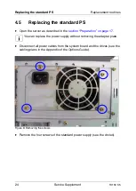
Page 24: ...bed in the section Preparation on page 17 I You can replace the power supply without removing the adapter plate Ê Disconnect all power cables from the system board and the drives see the cabling plans in the Appendix of the Options Guide Figure 6 Removing the screws Ê Remove the four screws of the standard power supply see the circles ...

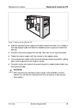
Page 25: ...ply into the bay Take care not to trap the cables Ê Fasten the power supply with four screws to the adapter plate Ê Connect all power cables to the system board and the drives see the cabling plans in the Appendix of the Options Guide Ê Close the server and connect all power plugs for a detailed description see the Options Guide V CAUTION After replacing the standard power supply a fan calibration...

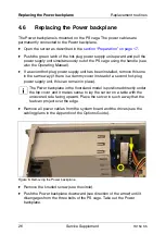
Page 26: ...lled remove this one in the same way if there is a dummy cover instead of a second hot plug power supply unit this can remain in place I The Power backplane in the floorstand model is positioned directly under the top cover and it makes sense to lay the server on a table with the uncovered side facing upward Place the server in such a way that the feet can project over the edge Ê Remove all power ...

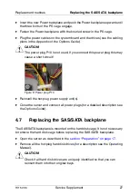
Page 27: ...ug this may cause a short circuit Figure 9 Power plug P10 Ê Reinstall the hot plug power supply unit s Ê Close the server and connect all power plugs for a detailed description see the Options Guide 4 7 Replacing the SAS SATA backplane The SAS SATA backplane is mounted on the hard disk cage It is not necessary to remove the hard disk cage before replacing the SAS SATA backplane Ê Open the server a...

Page 28: ...r with the holder out of the server Be careful with the isolation foil positioned on the rear side of the SAS SATA backplane Ê Remove the isolation foil and lift the SAS SATA backplane from the holder Ê Insert the new SAS SATA backplane in the holder Ê Position the isolation foil Ê Fasten the SAS SATA backplane holder using the four screws on the hard disk cage Ê Attach the connectors of the SMB c...

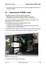
Page 29: ...e environment temperature The current temperature values and EEPROM data are transmitted to the system board via the connected I2C bus The IDTEMP combo must be correctly installed in order to monitor the temperature correctly to enable the server management to display the correct system picture to install the server using ServerStart The IDTEMP combo is situated on a separate holder under the hard...

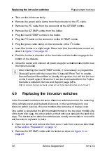
Page 30: ...D prom with the help of the ChassisIDProm Tool to enable ServerView and ServerStart to identify the system You will find the tool on the ServerSupport CD and or it can be downloaded from the Fujitsu Siemens Computers Service and Support page URL http extranet fujitsu siemens com service information intelservers tools 4 9 Replacing the intrusion switches In the floorstand model two intrusion detect...

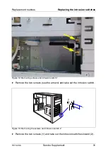
Page 31: ...intrusion switches Figure 12 Removing screws and intrusion switch 1 Ê Remove the two screws see the arrows and take out the intrusion switch Figure 13 Removing the screws and intrusion switch 2 Ê Remove the two screws 1 and take out the intrusion switches inward 2 2 1 ...

Page 32: ...Insert the intrusion switch with the two wires in its holder and fasten the switch with two screws Ê Reinsert the IDTEMP combo with its holder as shown in figure 11 on page 29 Ê Close the server and connect all power plugs for a detailed description see the Options Guide 4 10 Replacing the processor V CAUTION Processors are modules which can react extremely sensitively to electro static discharges...

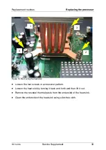
Page 33: ... Removing the heat sink Ê Loosen the four screws in a crossover pattern Ê Loosen the heat sink by turning it back and forth and then lift it out Ê Remove the residual thermal paste from the underside of the heat sink Ê Clean the underside of the heat sink using a lint free cloth 1 4 3 2 ...

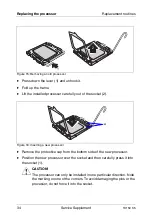
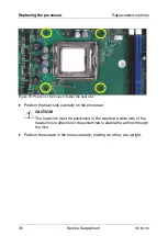
Page 34: ...out of the socket 2 Figure 16 Inserting a new processor Ê Remove the protective cap from the bottom side of the new processor Ê Position the new processor over the socket and then carefully press it into the socket 1 V CAUTION The processor can only be installed in one particular direction Note the marking on one of the corners To avoid damaging the pins or the processor do not force it into the s...

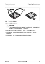
Page 35: ... 1 V CAUTION The processor holder must fall down by itself Do not close with force because soldering pads may be damaged Ê Press the lever slowly downward 2 until it is hooked in again 3 Ê Apply a small amount of thermal paste to the upper side of the new processor Ê Ensure a thin and even distribution of the thermal paste 1 2 3 ...

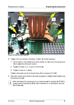
Page 36: ...o fasten the heat sink Ê Position the heat sink carefully on the processor V CAUTION The heat sink must be positioned in the way that a wide side of the heat sink is in direction of the system fan to enable the air flow through the ribs Ê Position the screws in the holes carefully making sure they are upright ...

Page 37: ...processor when tightening the next screws 2 Tighten screws no 2 3 and 4 in this order 3 Tighten screw no 1 finally Tighten all screws as far as they will go with a torque of 0 6 NM Ê Close the server and connect all power plugs for a detailed description see the Options Guide I After replacing the processor it is recommended to update the BIOS to ensure proper operation BIOS flash diskette for a d...

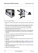
Page 38: ...th the uncovered side facing upward Place the server in such a way that the feet can project over the edge Ê Remove all external cables Ê Remove all controllers from their slots for a description see the Operating Manual and the Options Guide Take note of the slots of the controllers and the cabling Ê Remove the system fan see the section Replacing the system fan on page 22 Ê Remove the processor ...

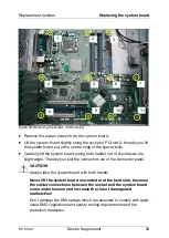
Page 39: ...rd using both hands out of the chassis in a slight angle Thereby you pull the connectors out of the connector panel V CAUTION Always take the system board with both hands Never lift the system board one sided or at the heat sink because the solder connections between the socket and the system board come under tension and increase the risk of damage and malfunction Don t damage the EMI springs whic...

Page 40: ...chassis Ê Adjust the system board If necessary adjust the position of the system board with a gentle twisting motion I When the system board is in the right position the centre rings engage with the holes indicated The centre rings are placed under the screw positions 1 and 5 Ê Fasten the system board with the eleven screws Ê Reconnect the cables to their original connectors see also the cabling p...

Page 41: ...er plugs for a detailed description see the Options Guide Ê Connect all external cables V CAUTION After installing the new system board it is necessary to update the system specific data BIOS iRMC firmware SDR sensor data record data to ensure proper operation BIOS flash diskette for a description see the BIOS Manual ...

Page 42: ......

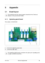
Page 43: ... system board is described in the Technical Manual of the system board D2399 5 1 1 Operating panel board Part number A3C40050401 I The operating panel board is included in the spare part operating panel module C26361 K644 Z331 1 Connector operating panel cable 2 Connector USB cable 2 1 ...

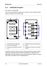
Page 44: ...ible on the front side of the mounting frames via light conductors which are situated at the mounting frames of the drives The controlling of the LEDs does only work if a driver has been loaded The signal of the LEDs is described in the Operating Manual 1 Connector power supply X6 4 SATA LED control connector X12 2 I2 C bus connector X11 5 LEDs 3 Connector to SAS SATA controller X1 6 SAS SATA conn...

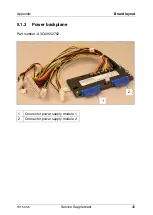
Page 45: ...TX150 S5 Service Supplement 45 Appendix Board layout 5 1 3 Power backplane Part number A3C40052762 1 Connector power supply module 1 2 Connector power supply module 2 1 2 ...

Page 46: ......

Page 47: ...o 29 intrusion detection switches 30 L light emitting diode LED 15 lithium battery 13 M meaning of the symbols 8 N notational conventions 8 note about the laser 15 O operating panel board 43 operating panel module 19 P Power backplane 26 45 processor 32 S SAS SATA backplane 27 44 standard PS 24 system board 38 T target group 5 ...

Page 48: ......

Page 49: ...0 S5 Server TX150 S5 Comments Suggestions Corrections Submitted by Fujitsu Siemens Computers GmbH User Documentation 81730 München Germany Fax 49 700 372 00000 email manuals fujitsu siemens com http manuals fujitsu siemens com ...

Page 50: ......

Page 51: ...0 S5 Server TX150 S5 Comments Suggestions Corrections Submitted by Fujitsu Siemens Computers GmbH User Documentation 81730 München Germany Fax 49 700 372 00000 email manuals fujitsu siemens com http manuals fujitsu siemens com ...

Page 52: ......

Page 53: ...tsu com Copyright Fujitsu Technology Solutions 2009 Hinweise zum vorliegenden Dokument Zum 1 April 2009 ist Fujitsu Siemens Computers in den alleinigen Besitz von Fujitsu übergegangen Diese neue Tochtergesellschaft von Fujitsu trägt seit dem den Namen Fujitsu Technology Solutions Das vorliegende Dokument aus dem Dokumentenarchiv bezieht sich auf eine bereits vor längerer Zeit freigegebene oder nic...

Reviews: