background image

14

PREPARATION

Switch on the main power switch.

Press the main POWER SWITCH at the rear. The power lamp lights (red).

Pressing this switch again switches off the power.

BASIC OPERATIONS

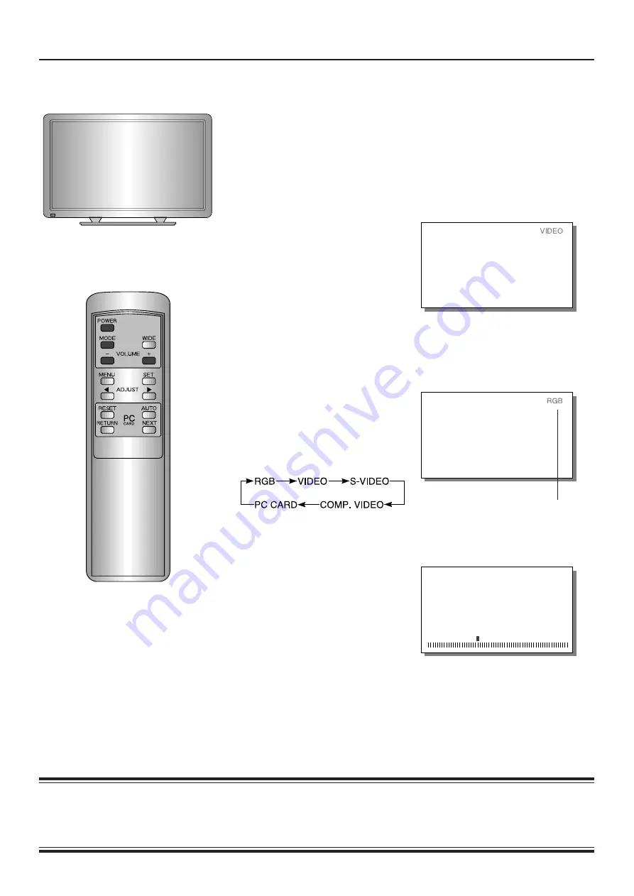
Mode display

• COMP.VIDEO stands for component video mode.

• NO CARD is displayed when there is no PC card in the PC card slot during PC CARD mode.

• When the speaker setting (see p.25) is OFF, SPEAKER OFF will be displayed if the VOLUME button is pressed.

Example:  VIDEO mode

Example:  When RGB selected

Mode display

1

Press the POWER button.

The power lamp changes from red

to green.

2

Select the VIDEO mode.

Select the video mode with the

MODE button.

Pressing the MODE button moves

the mode to the next item as

below.

 Adjusting the volume

Use the VOLUME buttons to adjust the

volume.

+ button····Raises the volume.

– button····Lowers the volume.

The current volume setting is  memo-

rized even when the power is

switched off.

This operation can also be

done using the buttons on the

Display’s operation panel.

Summary of Contents for PDS420E-H

Page 1: ...rom Falling 9 Usage Names of Parts and Their Functions 10 13 Basic Operations 14 Using PC Card 15 19 Viewing Wide Screen VIDEO Mode 20 21 Viewing Wide Screen RGB Mode 22 23 Handy Functions On Screen Display Setting 24 Internal Speaker Setting 25 WHITE BALANCE Setting 26 DPMS and Display Language Setting 27 Page Adjustments VIDEO Mode Video Adjustments 28 29 Screen Adjustments 30 31 Input Source Ad...

Page 2: ...82 2 1995 EN61000 4 2 1995 EN 61000 4 4 1995 EN61000 4 8 1993 ENV50140 1993 ENV50141 1993 ENV50204 1995 Safety e EN60950 1992 A1 1993 A2 1993 By conformance with the standard referenced the product follows the provisions of the directives listed below a EC Council Directive 89 336 EEC of 3rd May 1989 b EC Council Directive 92 31 EEC of 28th April 1992 c EC Council Directive 93 68 EEC of 22nd July ...

Page 3: ...structions should be retained for future reference All warnings on the product and in the operating instructions should be adhered to All operating instructions should be followed Unplug this product from the wall outlet before cleaning Do not use liquid cleaners or aerosol cleaners Use a damp cloth for cleaning Do not use attachments not recommended by the product manufacturer as they may be haza...

Page 4: ...ave fallen on the product c If the product has been exposed to rain or water d If the product does not operate normally by following the operating instructions Adjust only those controls that are covered by the Operation Manual as an improper adjustment of other controls may result in damage and will often require extensive work by a qualified technician to restore the product to its normal operat...

Page 5: ...E Programs can easily be created using a personal computer and the supplied Program Creation Software Use a PC card recommended by Fujitsu VERTICAL INSTALLATION The dynamic vertical screen is obtained by installing the Plasmavision vertically IDEAL FOR PERSONAL COMPUTER DISPLAY The Plasmavision supports VGA full display and SVGA compressed display A VARIETY OF INPUT TERMINALS The high quality imag...

Page 6: ...ES Connecting to External Equipment Cables for connecting external equipment must be purchased separately A B Screw A 10 mm Screw B 20 mm USER S MANUAL OPERATING GUIDE Cable clamper Attach as in the illustration Bundle connecting cables so that they lead downwards as in the illustration RS 232C RGB INPUT VIDEO INPUT COMPONENT VIDEO INPUT color difference input AUDIO INPUT SYNC SW TTL ANALOG 75Ω S ...

Page 7: ... that they do not get caught on anything For good heat dissipation the Plasmavision requires at least the space shown in the figure below The installation location must have an ambient temperature range of 0 C 40 C See page 49 for optional parts When desktop stand used When wall mounting unit used horizontally When ceiling mounting unit used WHAT YOU SHOULD KNOW Upper Left Right Wall 20 cm 5 cm 5 ...

Page 8: ...ing red it is warning that something is wrong with the Plasmavision There is a danger of fire or electrical shock so be certain to unplug the power cord and contact your product dealer See P52 The plasma display panel has been built using extremely precise and sophisticated technologies More than 99 99 of its pixels are effective However a minute number of pixels are missing or constantly lit Do n...

Page 9: ...brackets A and B with a strong rope so that the display panel does not topple over This arrangement is stable when the rope is horizontal or pulled downward ATTACHING TO DESKTOP STAND Fasten the screws supplied with the desktop stand into their holes at the rear of the desktop stand 2 holes For details refer to P 42TT01 User s Manual for the desktop stand Two places Screw B 20 mm The screws are su...

Page 10: ...r on or off MODE button Selects the input mode MENU button For adjusting the video and audio to your taste VOLUME ADJUST buttons Normally used for adjusting the volume During adjustments these buttons are used for making adjustments from the menu screen WIDE SET button Normally used for selecting the desired wide screen During adjustments this is the SET button for setting the menu screen PC CARD ...

Page 11: ... input terminal RGB INPUT Connects to the computer monitor s analog RGB output terminal Cables connecting the personal computer vary ac cording to the type of machine so consult your prod uct dealer AUDIO INPUT RGB INPUT RS 232C SYNC SW TTL ANALOG 75Ω CONPONENT VIDEO INPUT VIDEO INPUT S VIDEO INPUT R L RS 232C input terminal RS 232C Connects to the computer RS 232C output terminal Audio input term...

Page 12: ...When in PC CARD mode used to switch the program created with the accessory program creation soft ware to AUTO or MANUAL mode NEXT button P19 When in PC CARD mode moves to the next screen of the program created with the accessory program creation software The PC card s program creation software refers to the accessory PC Card Utility for Plasmavision For the adjustment menu see the pages below Hand...

Page 13: ...using high frequency fluorescent lights If this happens move away from those lights After it has been used for a long time the remote controller batteries go flat When this happens replace them with new ones When replacing the batteries make sure they are the same type as the originals 1 Press on the cover and slide in the direction of the arrow 2 Load two AA batteries taking care that the and end...

Page 14: ...ill be displayed if the VOLUME button is pressed Example VIDEO mode Example When RGB selected Mode display 1Press the POWER button The power lamp changes from red to green 2Select the VIDEO mode Select the video mode with the MODE button Pressing the MODE button moves the mode to the next item as below Adjusting the volume Use the VOLUME buttons to adjust the volume button Raises the volume button...

Page 15: ...ly this activity covers not only memory cards but all types of I O cards These cards are referred to as PC cards and their standardization PC Card Standard has been completed CAUTION Using the PC card Do not bend the card or subject it to strong mechanical shocks Do not use or store the card where static electricity or electrical noise can occur easily Do not use or store the card in hot humid dus...

Page 16: ...card insert the PC card into the PC card slot Insert the PC card for creating or storing programs with the accessory program creation software Push the PC card right into the slot until the button on the side of the card slot pops up Confirm that the PC card is inserted completely and close the door of the PC card slot Lock the door with the accessory key to prevent theft of the PC card CAUTION Do...

Page 17: ...estroy data on the card The access lamp lights while the PC card is being accessed 3Turn on the main power switch Press the main power switch to turn on the power The power lamp lights red Press POWER on the remote controller The power lamp changes from red to green 4Select PC CARD mode With the MODE button select PC CARD mode and execute the program For details see pages 18 and 19 Example PC CARD...

Page 18: ...ated will execute automatically as below Example PC CARD still picture display Example Display of current status MANUAL mode Example When AUTO mode is selected Last page AUTO When AUTO mode selected First page Second page When the PC card is being executed in AUTO mode the MENU button cannot be used If it is pressed the message INVALID OPERATION appears When adjusting do so after pressing the AUTO...

Page 19: ...ff before taking out the PC card Check the data written to the PC card with the accessory program creation software For details refer to the PC card s operation manual In MANUAL mode the color of the still picture can cause the picture to become jumbled when it is switched Fifth screen Sixth screen Seventh screen Seventh screen Sixth screen Fifth screen Seventh screen First screen 1Select PC CARD ...

Page 20: ...o the zoom screen automatically the display may take a few mo ments to switch to the zoom screen for the first dark scene AUTO mode cannot be selected in COMPONENT VIDEO mode In AUTO mode the contents of the video software are detected and the display switches to the optimum wide screen as follows WIDE 1 The appropriate wide screen for ordi nary video 4 3 software WIDE 2 Appropriate for 16 9 video...

Page 21: ...n modes When the selected mode has a different picture aspect ratio from the media to be viewed the picture will appear different from the original Keep this in mind when selecting the screen mode Note that use of a wide select function to change the screen size or aspect ratio during commercial use or for public viewing in a coffee shop hotel or the like may infringe on copyrights protected by th...

Page 22: ... current viewing mode is displayed 2Press the WIDE button to select the desired screen size Pressing the WIDE button moves the mode to the next item as below NORMAL WIDE Example NORMAL Example When WIDE is selected This operation can also be done using the buttons on the Display s operation panel ...

Page 23: ...tion to change the screen size or aspect ratio during commercial use or for public viewing in a coffee shop hotel or the like may infringe on copyrights protected by the copyright law To respect the intent of the creators of the original video use NORMAL mode In PC CARD mode the wide screen is invoked WIDE Vertically wide video ...

Page 24: ...e desired setting Pressing the ADJUST button moves the selection to the next item as below ON The mode is displayed on the screen for a few sec onds when the power is first switched on and when the mode is switched OFF The mode is not displayed Example When COMMON SETTINGS is selected Example When DISPLAY is selected Example When ON is selected To complete adjustments Press the MENU button to retu...

Page 25: ...n to the VIDEO MENU Pressing the MENU button returns the display to the previous screen and closes the adjustment screen Example When COMMON SETTINGS is selected Example When SPEAKER is selected Example When ON is selected Adjustment items Pressing the SET button moves the selection to the next item ON When using the internal speakers regardless of mode RGB When using the internal speakers in RGB ...

Page 26: ...play s operation panel 1Select COMMON SETTINGS from the VIDEO MENU screen 1 Press the MENU button 2 With the ADJUST button select COMMON SETTINGS 3 Set by pressing the SET button COMMON SETTINGS can be set in the same way from any mode menu 2Select the adjustment item With the SET button select WHITE BALANCE Pressing the SET button moves the selection to the next item as below 3Adjust to the desir...

Page 27: ...lected each time the SET button is pressed DPMS DPMS stands for Display Power Management Signaling It is a function that automatically reduces the amount of power consumed by the monitor When the power is on if no signal is input within the set time the power management function is triggered the monitor screen is automatically switched off and the monitor goes on standby This signal wait time can ...

Page 28: ...re button Makes the picture brighter button Makes the picture darker To adjust multiple items repeat Steps 2 and 3 Example When PICTURE is selected Example When BRIGHTNESS is selected Example When the button is pressed To complete adjustments Press the MENU button to return to the VIDEO MENU Pressing the MENU button returns the display to the previous screen and closes the adjustment screen The ad...

Page 29: ...olor more saturated button Makes the color less saturated TINT Color tint can be adjusted button Makes the tint greener button Makes the tint more purple SHARPNESS Picture sharpness can be adjusted button Makes a sharper picture button Makes a softer picture Adjustment items Pressing the SET button moves selection to the next item VIDEO mode is the generic term for VIDEO mode S VIDEO mode and COMP...

Page 30: ...oves the screen up button Moves the screen down For the adjustment range see the opposite page To adjust multiple items repeat steps 2 and 3 Example When POSITION SIZE is selected Example When VERTICAL POSITION is selected Example When the button is pressed To complete adjustments Press the MENU button to return to the VIDEO MENU Pressing the MENU button returns the display to the previous screen ...

Page 31: ...utton Adjustment items Pressing the SET button moves selection to the next item VERTICAL POSITION For VIDEO and S VIDEO modes ZOOM 15 through 15 Other 7 through 7 COMPONENT VIDEO mode 90 through 90 HEIGHT For VIDEO and S VIDEO modes 7 through 7 COMPONENT VIDEO mode 70 through 70 HORIZONTAL POSITION For VIDEO and S VIDEO modes 31 through 31 COMPONENT VIDEO mode 90 through 90 HORIZONTAL WIDTH For al...

Page 32: ... set for VIDEO mode and S VIDEO mode 3Set the connected equipment Select with the ADJUST button MODE 1 Use this mode for nor mal usage such as DVD BETACAM or other standard component video signals MODE 2 Use this mode only for MUSE signal Hi Vision Japanese high definition video signal Example When SOURCE is selected Example When MODE 1 is selected To complete adjustments Press the MENU button to ...

Page 33: ... saved for VIDEO mode and S VIDEO mode CLAMP PULSE When connecting a color difference signal to the COMPONENT VIDEO input terminal CLAMP PULSE must be set This setting switches the phase of the clamp pulse The ADJUST button can be adjusted in the range from 0 through 4 Select so the optimum picture is attained This setting can be done in COMPONENT VIDEO mode only Adjustment items Pressing the SET ...

Page 34: ...ries out automatic correction so that the video is optimum for viewing moving images STILL Carries out automatic correction so that the video is optimum for viewing still images Example When OTHERS is selected Example When MOTION is selected To complete adjustments Press the MENU button to return to VIDEO MENU Pressing the MENU button returns the display to the previous screen and closes the adjus...

Page 35: ...ewing moving images MODE2 Carries out automatic correction so that the video is optimum for viewing still images Adjustment items Pressing the SET button moves selection to the next item VIDEO mode is the generic term for VIDEO mode S VIDEO mode and COMPONENT VIDEO mode The adjustments are saved for each video mode If there is no operation for 60 seconds the screen display goes off ...

Page 36: ... below BRIGHTNESS CONTRAST 3Adjust to the desired picture button Makes the contrast stronger button Makes the contrast weaker To adjust another item repeat steps 2 and 3 Example When PICTURE is selected Example When CONTRAST is selected To complete adjustments Press the MENU button to return to the RGB MENU Pressing the MENU button returns the display to the previous screen and closes the adjustme...

Page 37: ...ton Makes the picture darker CONTRAST Screen contrast difference between dark and light can be adjusted button Makes the contrast stronger button Makes the contrast weaker Adjustment items Pressing the SET button moves the selection to the next item If there is no operation for 60 seconds the screen display goes off ...

Page 38: ... as below 3Adjust with the ADJUST button button Enlarges the screen button Reduces the screen The adjustment range is from 150 through 150 To adjust multiple items repeat steps 2 and 3 Example When POSITION SIZE is selected Example When HEIGHT is selected To complete adjustments Press the MENU button to return to the RGB MENU Pressing the MENU button returns the display to the previous screen and ...

Page 39: ... adjustment range is from 250 through 250 HORIZONTAL WIDTH When too small Adjust with the button When too large Adjust with the button The adjustment range is from 150 through 150 VERTICAL LINE The number of vertical lines on the screen can be set With the ADJUST button select the number of vertical lines Pressing the ADJUST button moves the selection to the next item as be low Adjustment items Pr...

Page 40: ...ltiple items repeat steps 2 and 3 Example When SOURCE is selected Example When MAC MODE is selected Example When MODE1 is selected To complete adjustments Press the MENU button to return to the RGB MENU Pressing the MENU button returns the display to the previous screen and closes the adjustment screen EXAMPLE SETTING MACINTOSH MODE The Apple Macintosh has two dot clocks If the display is partly c...

Page 41: ... For details see Personal Computers that Can Be Connected on page 48 When no signal is detected NO SIGNAL is displayed Adjustment items Pressing the SET button moves selection to the next item Set CLAMP PULSE as follows depending on the connected device signal 0 Normal 1 MUSE signal Hi Vision Japanese high definition video signal 2 Other 3 MAC 4 NTSC PAL SECAM Points about usage Depending on the t...

Page 42: ... MODE1 Carries out automatic correction so that the video is optimum for viewing moving images MODE2 Carries out automatic correction so that the video is optimum for viewing still images To adjust multiple items repeat steps 2 and 3 Example When OTHERS is selected Example When GRADATION is selected To complete adjustments Press the MENU button to return to the RGB MENU Pressing the MENU button re...

Page 43: ...e of the personal computer the screen may become blurred If so adjust The ADJUST button can be adjusted in the range from 0 through 15 SYNC PHASE The screen may tremble vertically If so use the ADJUST button to adjust the screen within the range of 2 and 1 Adjustment items Pressing the SET button moves selection to the next item When GRADATION is automatically recognized in SVGA mode it cannot be ...

Page 44: ...as below BRIGHTNESS CONTRAST 3Adjust to the desired picture button Makes the contrast stronger button Makes the contrast weaker To adjust another items repeat steps 2 and 3 Example When PICTURE is selected Example When CONTRAST is selected To complete adjustments Press the MENU button to return to the PC CARD MENU Pressing the MENU button returns the display to the previous screen and closes the a...

Page 45: ...contrast stronger button Makes the contrast weaker Adjustment items Pressing the SET button moves selection to the next item The MENU button is not effective during AUTO mode of PC CARD mode If the MENU button is pressed the message INVALID OPERATION will be displayed The MENU button cannot be used if the video or RGB signals are included in the program in PC CARD mode If there is no operation for...

Page 46: ...on MODE1 Carries out automatic correction so that the video is optimum for viewing moving images MODE2 Carries out automatic correction so that the video is optimum for viewing still images To adjust multiple items repeat steps 2 and 3 Example When OTHERS is selected Example When GRADATION is selected Example When the MODE 2 is selected To complete adjustments Press the MENU button to return to th...

Page 47: ...rough 5 CLOCK PHASE Depending on the clock phase of the personal computer the screen may become blurred If so adjust The ADJUST button can be adjusted in the range from 0 through 15 Adjustment items Pressing the SET button moves selection to the next item The MENU button is not effective during AUTO mode of PC CARD mode If the MENU button is pressed the message INVALID OPERATION will be displayed ...

Page 48: ...ignals Mode Display Horizontal frequency Vertical frequency Supported signal number dots lines kHz Hz 1 852 480 31 72 59 97 Note1 When dedicated graphics board used 2 640 480 31 47 59 94 VGA 3 640 480 37 86 72 81 VGA 72 Hz 4 640 480 37 50 75 00 VGA 75 Hz 5 720 400 31 47 70 09 VGA 400 lines 6 640 480 34 97 66 61 MAC 13RGB 1 640 480 35 00 66 67 MAC 13RGB 2 7 640 400 24 83 56 42 PC98 24kHz 8 640 400 ...

Page 49: ... H Graphics board When a graphics board is used P 42GA04 with a DOS V personal computer an 852 dot x 480 line wide screen can be displayed AV terminal unit This is a dedicated PDS4204E H P 42TE01 B AV terminal unit Before attaching pull out the power plug When installing an optional product follow the directions in the optional product user s or installation manual The colors of the Plasmavision a...

Page 50: ...S terminal Y 1Vp p 75 Ω C 0 286Vp p 75 Ω Component video input Three BNC terminals Y 1Vp p 75 Ω Pb B Y 0 7Vp p 75 Ω Pr R Y 0 7Vp p 75 Ω Compatible format NTSC PAL SECAM N PAL M PAL 4 43NTSC PC RGB input One 15 pin 3 row mD sub terminal Video signal 0 7Vp p 75 Ω SYNC signal TTL level or 0 3 Vp p 75 Ω PC card PCMCIA Rel 2 0 JEIDA Ver 4 0 or later 5 V ATA card Type I III Audio Audio input One system ...

Page 51: ...erminal Display is RS 232C Connects to a personal computer RS 232C terminal The sync switch TTL ANALOG switch is on the rear of the 13 pin hori zontal sync and 14 pin vertical sync terminals Points about shipping The Plasmavision is a precision instrument and requires dedicated packing materials for shipping Use Fujitsu s packing materials only Regulation PDS4204W H PDS4204E H UL CSA Safety UL1950...

Page 52: ...Do any of the video settings need readjusting There is no sound Are the internal speakers switched off ERROR MESSAGE CONDITION 1 is displayed The fan is malfunctioning Switch off the power ERROR MESSAGE CONDITION 2 is displayed The temperature inside the set has risen far too high Switch off the power The power can be turned on once the temperature lowers INVALID CARD is displayed Is the inserted ...

Reviews: