MB95630H Series
174
FUJITSU SEMICONDUCTOR LIMITED
MN702-00009-1v0-E
CHAPTER 11 8/16-BIT COMPOSITE TIMER
11.15 Notes on Using 8/16-bit Composite
Timer
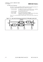
Figure 11.15-1 Operations of Counter in Standby Mode or in Pause
(Not Serving as PWM Timer)
Figure 11.15-2 Operations of Counter in Standby Mode or in Pause
(Serving as PWM Timer)
Co
u
nter v
a
l
u
e
0xFF
0x
8
0
0x00
Tn0DR/Tn1DR d
a
t
a
regi
s
ter v
a
l
u
e (0xFF)
Timer cycle
Time
IF
b
it
S
TA
b
it
IE
b
it
S
LP
b
it
(
S
TBC regi
s
ter)
S
TP
b
it
(
S
TBC regi
s
ter)
W
a
ke-
u
p from
s
top mode
b
y extern
a
l interr
u
pt
HO
b
it
S
top mode
W
a
ke-
u
p from
s
leep mode
b
y interr
u
pt
Oper
a
tion re
a
ctiv
a
ted
Oper
a
tion h
a
lt
s
Del
a
y of o
s
cill
a
tion
s
t
ab
iliz
a
tion w
a
it time
Interv
a
l time
a
fter w
a
ke-
u
p
from
s
top mode (indetermin
a
te)
Re
qu
e
s
t end
s
HO re
qu
e
s
t
HO re
qu
e
s
t end
s
Oper
a
tion re
su
me
s
S
leep mode
Cle
a
red
b
y progr
a
m
Co
u
nter v
a
l
u
e
0xFF
0x00
Tn0DR/Tn1DR v
a
l
u
e (0xFF)
Time
S
TA
b
it
PWM timer o
u
tp
u
t pin
(0xFF)
S
LP
b
it
(
S
TBC regi
s
ter)
S
TP
b
it
(
S
TBC regi
s
ter)
S
leep mode
*
*: The PWM timer o
u
tp
u
t m
a
int
a
in
s
the v
a
l
u
e held
b
efore it enter
s
the
s
top mode.
HO
b
it
M
a
int
a
in
s
the level prior to hold
M
a
int
a
in
s
the level prior to
s
top
W
a
ke-
u
p from
s
top mode
b
y extern
a
l interr
u
pt
W
a
ke-
u
p from
s
leep mode
b
y interr
u
pt
Del
a
y of o
s
cill
a
tion
s
t
ab
iliz
a
tion w
a
it time


