


MB39A104
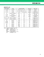
24
■
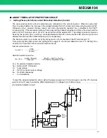
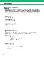
SELECTION OF COMPONENTS
• P-ch MOS FET
The P-ch MOSFET for switching use should be rated for at least 20% more than the maximum input voltage. To
minimize continuity loss, use a FET with low R
DS(ON)
between the drain and source. For high input voltage and
high frequency operation, on/off-cycle switching loss will be higher so that power dissipation must be considered.
In this application, the Toshiba TPC8102 is used. Continuity loss, on/off switching loss, and total loss are
determined by the following formulas. The selection must ensure that peak drain current does not exceed rated
values, and also must be in accordance with overcurrent detection levels.
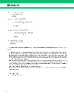
Continuity loss : P
C
On-cycle switching loss : P
S
(
ON
)
Off-cycle switching loss : P
S
(
OFF
)
Total loss : P
T
P
T
=
P
C
+
P
S
(
ON
)
+
P
S
(
OFF
)
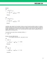
Example: Using the Toshiba TPC8102
CH1
Input voltage V
IN
(
Max
)
=
19 V, output voltage V
O
=
5 V, drain current I
D
=
3 A, Oscillation frequency f
OSC
=
500 kHz, L
=
15
µ
H, drain-source on resistance R
DS
(
ON
) := 50 m
Ω
, tr
=
tf := 100 ns.
Drain current (Max) : I
D
(
Max
)
Drain current (Min) : I
D
(
Min
)
P
C
=
I
D
2
×
R
DS
(
ON
)
×
Duty
P
S
(
ON
)
=
V
D
(
Max
)
×
I
D
×
tr
×
f
OSC
6
P
S
(
OFF
)
=
V
D
(
Max
)
×
I
D
(
Max
)
×
tf
×
f
OSC
6
I
D
(
Max
)
=
I
O
+
V
IN
−
V
O
ton
2L
=
3
+
19
−
5
×
1
×
0.263
2
×
15
×
10
−
6
500
×
10
3
:= 3.25 (A)
I
D
(
Min
)
=
I
O
−
V
IN
−
V
O
ton
2L
=
3
−
19
−
5
×
1
×
0.263
2
×
15
×
10
−
6
500
×
10
3
:= 2.75 (A)
Summary of Contents for MB39A104
Page 38: ...MB39A104 38 MEMO ...
Page 39: ...MB39A104 39 MEMO ...


