background image

E-26

CONNECTING THE DISPLAY TO EXTERNAL EQUIPMENT (Continued)

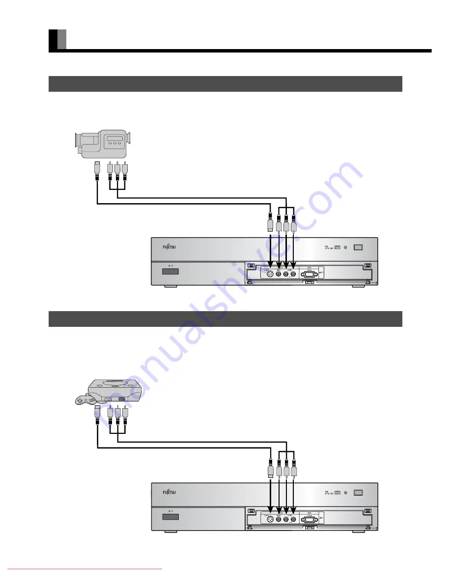
• A video camera can conveniently be connected to the Video 3 input on the front side. 
• Connect the video signal cable to either the S-video input terminal or the video input terminal. 
• If the unit to be connected is equipped with S-video output terminal, it is recommended to connect to the S-video terminal.

• As the connecting cable differs with videogame machines, please consult the instructions for your videogame machine. 
• Connect the video signal cable to either the S-video input terminal or the video input terminal. 
• Ensure that the same image (pattern) is not displayed on the screen for an extended period. If the same image is displayed on the screen for 

an extended period, the brightness of that part of the screen may change and image burn-in may leave an after-image on the screen. 

• If the videogame machine to be connected is equipped with S-video output terminal, it is recommended to connect to the S-video terminal.

VIDEO CAMERA

VIDEOGAME MACHINE

To video and audio outputs

To S-video output

To video and audio inputs

To S-video input

Front side of AV Selector

To video and audio outputs

To S-video output

To video and audio inputs

To S-video input

Front side of AV Selector

Downloaded From projector-manual.com Fujitsu Manuals

Summary of Contents for LPF-D711W

Page 1: ... 40 ADJUSTING SCREEN POSITION AND SIZE E 46 OTHER ADJUSTMENTS E 47 INITIALIZATION OF USER ADJUSTMENT VALUE E 53 CLEANING AND MAINTENANCE E 54 Others OPTIONS E 59 MAIN SUPPORTED SIGNALS E 60 SPECIFICATION E 61 Before using the display read this manual carefully so that you know how to use the display correctly Refer to this manual whenever questions or problems about operation arise Be sure to read...

Page 2: ...ct observe the following basic rules for its installation use and service Please read these Important Safeguards carefully before use 1 Read these instructions 2 Keep these instructions 3 Heed all warnings 4 Follow all instructions 5 Do not use this apparatus near water 6 Clean only with dry cloth 7 Do not block any ventilation openings Install in accordance with the manufacturer s instructions 8 ...

Page 3: ...ent damage to the product due to lightning and power line surges Do not overload wall outlets extension cords or convenience receptacles on other equipment as this can result in a risk of fire or electric shock Never push objects of any kind into this product through openings as they may touch dangerous voltage points or short out parts that could result in a fire or electric shock Never spill liq...

Page 4: ...andard PC to the RGB input terminal In this case contact your dealer for more information The protective circuit built into the display automatically turns off the power if the display has a problem In this case you will see that the power indicator lamp flashes red or green The ventilation should not be impeded by covering the ventilation openings with items such as newspapers table cloths curtai...

Page 5: ... s ġུġࢊ Póññêèé Ё CHECKING ACCESSORIES Two power cables One System cable PICTURE Three ferrite cores One remote control Two AAA batteries One user s manual Manual Four air filters Two Antivibration cushions Downloaded From projector manual com Fujitsu Manuals ...

Page 6: ...ight source lamp with a new one For the method of replacing the light source lamp see page E 56 Make sure that the grounding work should be performed only by a professional electrician Be sure to make the grounding connection before inserting the power plug into the receptacle When removing the grounding connection pull out the power plug from the receptacle beforehand TRANSPORTATION LIGHT SOURCE ...

Page 7: ...the projector so that proper ventilation is maintained Check the air filters and lamp protection filter for accumulation of dust If they are soiled clean them or replace them with new ones see page E 54 If the abnormal condition persists despite the above measures call your dealer for service The power indicator lamp and temperature lam indicator lamp light up in red The light source lamp will not...

Page 8: ...ed to direct sunlight This projector unit uses an LCD panel to project pictures on the screen Please note therefore that the projected picture may differ from that of the CRT indicator lamp of television and personal computer in color tone and contrast When purchasing a projection screen carefully check the characteristics to select one that best suits your purpose of use Do not use a polarizing s...

Page 9: ...nt an accident and ensure safety in the event of an earthquake fix the display securely into position as described below To ensure proper heat radiation provide at least as much space around the display as shown below Be sure to install the projector at a place that can keep the ambient temperature ranging from 5 to 35 Run the power cords and connection cables along the wall and at the corners of ...

Page 10: ...inch Height cm Width cm Minimum m Maximum m Vertical cm Horizontal cm 60 74 7 132 8 2 26 2 85 4 15 7 52 70 87 2 155 0 2 65 3 35 4 85 8 78 80 99 6 177 1 3 04 3 84 5 54 10 03 90 112 1 199 2 3 43 4 34 6 23 11 28 100 124 5 221 4 3 82 4 84 6 92 12 54 110 137 0 243 5 4 21 5 33 7 62 13 79 120 149 4 265 7 4 60 5 83 8 31 15 05 130 161 9 287 8 4 99 6 32 9 00 16 30 140 174 3 309 9 5 38 6 82 9 69 17 55 150 18...

Page 11: ...from the ceiling request ask your dealer for help Do not use mounting fittings other than specified by the manufacturer Otherwise risk of the projector falling from the ceiling personal injury fire and electric shock will result Use the receptacle near the projector unit that allows easy connection and disconnection of the projector s power plug When installing the projector to a place on a perman...

Page 12: ...ctor using the special cable provided ٤ l power switch If this switch is pressed when the power indicator lamp is off the indicator lamp will light The power can be turned on and the standby mode selected by using the remote control or the control panel of the display If this switch pressed when the power indicator monitor is lit will go out Power input terminal Connect the power cable supplied wi...

Page 13: ...cus button Adjusts the size and focus of the picture Menu button MENU Shows the menu display for adjusting the picture 4 way button Selects the item and adjusts the value in the Menu display Enter button Fixes the entry in the ADJUSTMENT MENU PROJECTOR SECTION TOP Warning If the power indicator lamp flashes red or green this signifies that the display has developed a problem When this happens be s...

Page 14: ...ideo3 S video input terminal Connect this terminal to the S video output terminal of your video camera etc Video3 video input terminal Connect this terminal to the video output terminal of your video camera etc Audio input terminals L R These are the audio input terminals for the Video3 and RGB3 terminals Input the audio for the video to be seen here RGB3 input terminal Connect this terminal to yo...

Page 15: ...Video6 input terminal Connect this terminal to the component video output terminal of your DVD etc Video 7 input terminal Connect this terminal to HDMI output terminal of your DVD RGB1 input terminal Connect this terminal to the monitor DVI D output terminal of your PC RGB2 input terminal Connect this terminal to the monitor mD sub output terminal of your PC RS 232C input terminal Connect this ter...

Page 16: ...S Clock Shield 7 DDC Data 15 Ground for 5V 23 T M D S Clock 8 16 Hot Ploug Detect 24 T M D S Clock mD sub input terminal RGB2 3 INPUT mD sub Pin No Input signal Pin No Input signal 1 Red 9 2 Green 10 Ground 3 Blue 11 4 12 5 Ground 13 Horizontal synchronization 6 Ground 14 Vertical synchronization 7 Ground 15 8 Ground Frame Ground HDMI input terminal VIDEO7 Pin No Input signal Pin No Input signal 1...

Page 17: ... Press this button to display the Program No input mode and screen size status The status is displayed for about five seconds CDEF Adjustment buttons Î E 38 E 53 Use these buttons to select the item or adjust the value in the Menu screen Enter button Î E 38 E 53 Press this button to fix the entry in the ADJUSTMENT MENU SET UP button Î E 35 Press this button to make lens shift screen reverse and ke...

Page 18: ...To remove the cover slide it outwards while pressing it down 2 Place two AAA batteries Pay attention to set them in correct pole 3 Close the cover until it snaps into place PRECAUTIONS CAUTION Be sure to use replacement batteries of the same type as the original ones When disposing of used batteries please comply with governmental regulations or environmental public institution s rules that apply ...

Page 19: ...he remote control and the display s signal receiver EFFECTIVE RANGE FOR THE REMOTE CONTROL Left Upper Lower Right 5 m Front Left Right 5 m Front Upper Lower Note The remote control may not function properly if you use a high frequency fluorescent lamp If you experience problems move the lamp or use the remote control from a different position Downloaded From projector manual com Fujitsu Manuals ...

Page 20: ...ke sure that all connectors are securely inserted into their terminals Never force to bend the power cords or cables Otherwise they may cause damage These ferrite cores are used to attenuate undesired signals Attach them correctly as shown in the following illustrations One ferrite core For AV SELECTOR When connecting a cable to the power input terminal attach one of these ferrite cores to the cab...

Page 21: ...SELECTOR Rear side of projector To AC outlet Power input terminal Picture terminal Power input terminal Rear side of AV selector Picture terminal To AC outlet System cable PICTURE Note Never force to bend the power cords or cables Otherwise they may cause damage Downloaded From projector manual com Fujitsu Manuals ...

Page 22: ...omponents See P Î AV Selector Audio amplifier Î E 28 Video camera Î E 26 Videogame machine Î E 26 Satellite tuner Î E 25 DVD recorder player Î E 24 To AC outlet To AC outlet Note Unplug the power cord from the AC outlet before you connect external components Also refer to the instructions for the component to be connected The projector unit has no speaker function To produce sound connect it to an...

Page 23: ...to connect to the S video terminal VCR To video output To S video output To audio outputs To S video input To audio inputs To video input Rear side of AV Selector Note Unplug the power cord from the AC outlet before you connect external components Also refer to the instructions for the component to be connected When inputting audio connect to the terminals corresponding to the used video input or ...

Page 24: ...nt to be connected is equipped with the HDMI output terminal or the component picture output terminal connection to either of these terminals is recommended DVD RECORDER PLAYER To S video output To video output To component video output To audio outputs To video input To S video input To audio inputs To component video input Rear side of AV Selector To HDMI input To HDMI output Downloaded From pro...

Page 25: ... terminals is recommended SATELLITE TUNER To S video output To video output To component video input To audio outputs To video input To S video input To audio inputs To component video output Rear side of AV Selector BS 110 degree CS Antenna UHF Antenna To HDMI output To HDMI input Note Unplug the power cord from the AC outlet before you connect external components Also refer to the instructions f...

Page 26: ...al or the video input terminal Ensure that the same image pattern is not displayed on the screen for an extended period If the same image is displayed on the screen for an extended period the brightness of that part of the screen may change and image burn in may leave an after image on the screen If the videogame machine to be connected is equipped with S video output terminal it is recommended to...

Page 27: ...sub To RGB output DVI D To audio output To mD sub input To DVI D input When connecting to the front side of the AV Selector To audio input To RGB output mD sub To audio output To mD sub input When connecting to the rear side of the AV Selector Note Unplug the power cord from the AC outlet before you connect external components Also refer to the instructions for the component to be connected The pr...

Page 28: ...o output terminal see the audio input selection page E 50 The signal input as digital input is not output as analog audio The digital audio input terminal on the display complies with a sampling frequency of 48 kHz In the case of outputs with another frequency connect to an audio system amplifier WHEN OUTPUTTING AUDIO SIGNALS TO AN AUDIO AMPLIFIER Rear side of AV Selector To digital audio input To...

Page 29: ...d side of AV selector s front The power indicator lamps of both the projector and AV selector light up 2 Press The color of the power indicator lamp turns from Red to Green The indicator lamp blinking in orange on the projector indicates that the lamp is let to cool Note For one minute after the light source lamp lights up another press of POWER button will not turn off the power Downloaded From p...

Page 30: ...ght source lamp cannot be lighted again After one minute the lamp can be turned on again 3 When the cooling is completed the fan stops operation and then the power monitor indicator lamp turns on in red resulting in the standby mode Even after the power is turned to standby mode the cooling fan continues rotating while high temperature remains inside the projector for approximately 2 minutes While...

Page 31: ...eyond the range of adjustment FINE ADJUSTING THE SCREEN POSITION 1 Press The adjustment menu display appears 2 Press CD to select Lens Shift 3 Press The adjustment display appears 4 Press EFCD to fine adjust the screen position Once this button is pressed the adjustment operation halts This means an operation to make fine adjustment with ease Use this function at the time of fine adjustment This f...

Page 32: ...e portion of the picture Pressing F corrects the distortion of the right side portion of the picture 5 Press to register the adjustment result You can also use the buttons on the projector s control panel to perform these steps Installation menu screen Note Adjustment of either of the vertical or horizontal axis restricts the adjustment range of the other For example if the horizontal axis is adju...

Page 33: ...ay appears 2 Press CD to select Reverse Mode 3 Press The adjustment display appears 4 Press EF to reverse the picture as desired 5 Press to register the adjustment result You can also use the buttons on the projector s control panel to perform these steps Installation menu screen Downloaded From projector manual com Fujitsu Manuals ...

Page 34: ...mponent video VIDEO3 Video S video VIDEO4 Video S video Component video VIDEO5 Component video VIDEO6 Component video VIDEO7 HDMI For selection of the input terminal see SETTING THE INPUT TERMINALS on P E 49 RGB INPUT MODE 1 Press to select the input mode You can select between the modes from RGB1 to RGB3 The input terminal of each RGB mode is as follows RGB1 DVI D RGB2 mD sub RGB3 mD sub Video1 m...

Page 35: ...emories 1 8 Each time this button is pressed the setting changes as follows For the method of storing the picture adjustment settings in memory see Picture Memory on page E 41 ZOOM FOCUS button Press The size and focus of the picture can be adjusted See the section ADJUSTING THE FOCUS AND SIZE OF THE PICTURE page E 31 for setting zoom and focus SET UP button Press The lens shift screen reverse and...

Page 36: ...e with this display Remember that if you select a mode with an aspect ratio ratio of frame width to frame height different from that of the TV program or video media the pictures will appear differently than if you had selected a mode having the same aspect ratio Showing a movie or similar premium event at a different aspect ratio from its original one at any event site restaurant or bar for profi...

Page 37: ...aption Captions may not be easy to read however depending on the picture The following aspect ratios are available 4 3 aspect ratio 16 9 aspect ratio VHF UHF broadcasting BS broadcasting HDTV broadcasting 1 85 1 aspect ratio 2 35 1 aspect ratio Vista Vision size Cinema Vision size SCREEN SIZE ASPECT RATIO Picture of standard size Wide1 Vertically extended picture Wide2 Horizontally extended pictur...

Page 38: ... 45 24 Frame Mode E 45 Picture Memory E 41 30 Frame Mode E 45 Default Jaggies Filter E 45 Motion Setting E 45 Position E 46 Size E 46 Default Reverse Mode E 33 Lens Shift E 31 Set Up E 35 Correct Keystone E 32 Zoom Focus E 35 Lamp Timer E 57 Adjustment E 47 On Screen Menu E 48 Dot Clock E 47 Input Terminal E 49 Clock Phase E 47 Others E 50 Clamp Position E 47 Auto Calibration E 47 OSD E 48 Languag...

Page 39: ... change tint values F More greenish colors E More purplish colors 6 Press to store 7 Press when you finish Repeat steps 3 4 5 and 6 when you wish to make changes to other options When is pressed after you have selected Default the settings are returned to those that were valid when you purchased the set Press to halt the operation in progress PICTURE selected in the main menu screen Tint selected ...

Page 40: ...e the tint to a more purplish color Press to store Adjusting the Sharpness Press F to sharpen the Sharpness Press E to soften the Sharpness Press to store Setting the Picture Mode Picture mode changes by pressing E or F and the optimumǫ curve for each picture mode shall be set up automatically Natural Displays a screen with detailed contrast Fine Suitable for watching a dark picture such as a movi...

Page 41: ...tor unit is shipped out of the factory the following recommended settings are stored in the picture memories 4 8 Picture memory 4 Suitable for viewing the picture of PC Picture memory 5 Similar picture to CRT screen Picture memory 6 Suitable for viewing normal moving picture Picture memory 7 Suitable for viewing a dark picture such as movies Picture memory 8 Suitable for viewing digital broadcast ...

Page 42: ...essed the setting is switched On Off Press to store Setting 3D NR This enables noise reduction processing with respect to the input signal noise level reduces screen flicker for more comfortable viewing Each time you press E or F the available choices appear in the following sequence Press to store Setting CODEC NR This enables noise reduction processing of mosquito noise or block noise generated ...

Page 43: ...following sequence 3500 More reddish colors 3500 More bluish colors User User Color Temp setup Press to store Setting User Color Temp Use C or D to select Red Green or Blue and adjust the color temp for each Press F to strengthen the selected color Press E to weaken the selected color Press to store Note The screen display disappears if there is no operation within approximately 60 seconds Dependi...

Page 44: ...orrections with respect to the range from yellow to cyan Bluish color With blue at the center performs corrections with respect to the range from cyan to magenta Targeting Red This function corrects the hue and color depth with respect to Red Tint Use E and F to adjust the hue Color Use E and F to adjust the color depth Press to store Adjustments can be made in the same way for Targeting Yellow Pe...

Page 45: ... thus enabling a smoother motion picture display Each time E or F is pressed the setting is switched Auto Off Press to store Motion Setting The detecting sensitivity for motion picture is set The response of the picture processing is valued in the motion picture priority setting Press F to specify still picture priority Press E to specify motion picture priority Press to store Progressive Scan Set...

Page 46: ...ing on the input signal Adjusting Screen Position Position Horizontal position Horizontal F Moves screen to the right E Moves screen to the left Vertical position Vertical C Moves screen up D Moves screen down Press to store Adjusting Screen Size Size Screen width Width F Increases width E Reduces width Screen height Height C Increases height D Reduces height Press to store You cannot adjust scree...

Page 47: ... ADJUSTMENT Adjustment Item Contents of Adjustments Operation Dot Clock mD sub You may find the vertically striped pattern in pictures depending on the clock frequency of your PC s processor If you experience blurring you can obtain a clearer picture by adjusting the Dot Clock Use EF to adjust to minimize vertically striped pattern in pictures Clock Phase mD sub Pictures and the outline of letters...

Page 48: ...he menu is displayed in the selected language Selection of indications Name Select You can change the settings for indications for video inputs and RGB inputs Video input You can change the settings for indications for the VIDEO inputs Select the desired indication in accordance with the connected equipment Each time E F is pressed the setting is switched In the case of VIDEO1 Press to store RGB i...

Page 49: ...ve priority in the order of Component Video S video and Video Component video input is not made to Video 3 Video Format You can use this option to select the video format appropriate for the input signal Each time you press E or F one of the available modes appears in the following sequence Auto1 Automatically selects NTSC PAL and SECAM Auto2 Automatically selects NTSC and M PAL Other than Auto Yo...

Page 50: ...input selection The input audio signal can be switched over from analog to digital Each time E or F is pressed the input signal changes in the following sequence When other than HDMI input is selected When HDMI input is selected Press to store OTHER SETTINGS Auto Off NO SIG settings screen Audio Input signal selection screen Analog Digital 1 Digital 2 HDMI Digital 1 Digital 2 Downloaded From proje...

Page 51: ...gnal is input the background color can be changed to blue Each time E or F is pressed the background color changes over Press to store Setting Exhibition Mode Exhibition Mode You can use this option to display the enhanced contrast to demonstrate the projector s bright high contrast picture Each time you press E or F one of the available choices appears in the following sequence On Off Press to st...

Page 52: ...on screen will appear Mode Input mode appears at the upper right corner of the screen Freq Scan Mode Frequency scanning Input Signal Video mode Input Sync Signal type Freq Synchronized signal frequency polarity Preset No RGB code number Information screen Video Mode Information screen RGB Mode Downloaded From projector manual com Fujitsu Manuals ...

Page 53: ... the Yes 5 Press The message Existing data are cleared is displayed The screen is displayed in English language 6 Press when you finish FACTORY DEFAULT selected in the main menu screen Displays the message of whether to proceed the initialization Displays the message of having completed the initialization Note The screen display disappears if there is no operation within approximately 60 seconds D...

Page 54: ...the projector may lead to electric shock or burns if touched PRECAUTIONS ON AIR FILTERS AND LAMP PROTECTION FILTER CLEANING THE AIR FILTERS AND LAMP PROTECTION FILTER 1 Unplug the power cord from the receptacle 2 Turn the projector upside down Pay attention to avoid scratches over the cover by laying a thick towel and other soft cloth under the projector 3 Remove the two screws marked with χ and t...

Page 55: ...ce of the lens easily gets scratched and do not rub or tap it with a hard object REPLACING THE AIR FILTERS 1 Unplug the power cord from the receptacle 2 Turn the projector upside down Pay attention to avoid scratches over the cover by laying a thick towel and other soft cloth under the projector 3 Unscrew three screws marked χ symbol to remove the filter holder 4 Replace the air filters with new o...

Page 56: ...n Lay a thick towel and other soft cloth under the projector lest it should get scratched 3 Remove the two screws marked with χ and then hold the knob of the lamp unit cover to remove it from the projector To ensure safety the safety device prevents the power from being turned on accidentally during the lamp replacement work CHANGING THE LAMP Warning Do not remove any screws other than those speci...

Page 57: ...cator lamps blink for a few seconds The lamp timer is initialized to 0 When replacing the lamp unit do not touch the glass inside the projector Dust and fingerprints sticking to the glass may deteriorate the luminous intensity of the light source lamp and shorten its life Replace lamp unit with a new one Loosen two screws Note For replacement be sure to use a lamp unit specified by the manufacture...

Page 58: ...ries Check for distance from the display Check whether you are pointing the remote control transmitter properly at the display s receiver Check for any obstacle between the remote control and the display The display makes a snapping sound This sound is produced when the cabinet expands or contracts due to variations in temper ature This sound does not indicate that the display has a problem The di...

Page 59: ...ons to be initially installed or installed at a different location by your dealer Note When installing an option make sure that all installation requirements for that option as given in the relevant instruction manual are met The colors of options do not match the display colors perfectly To improve the function and performance of optional accessories specifications and part names may change Consu...

Page 60: ...7 88 60 32 SVGA 60 Hz 800 x 600 46 88 75 00 SVGA 75 Hz 800 x 600 53 67 85 06 SVGA 85 Hz 1024 x 768 48 36 60 00 XGA 60 Hz 1024 x 768 60 02 75 03 XGA 75 Hz 1024 x 768 68 68 84 99 XGA 85 Hz 1280 x 1024 63 98 60 02 SXGA 60 Hz 1280 x 1024 79 98 75 03 SXGA 75 Hz 1600 x 1200 75 00 60 00 UXGA 60Hz 848 x 480 31 02 60 00 852 x 480 31 72 59 97 1360 x 768 47 71 60 01 720 x 485 15 73 59 94 60 fields 720 x 575 ...

Page 61: ...umber of pixels 2 072 600 pixels x 3 1 920 x 1 080 pixels x 3 Projection lens Motor operated zoom lens F 1 8 2 1 motor operated vertical and horizontal lens shift Light source lamp 250W Projection screen size 60 inches 200 inches Projection screen size of 120 to 150 inches is recommended Projection distance 1 0m 13 1m Aspect ratio 16 9 wide Projection system Vertical and horizontal screen reverse ...

Page 62: ...DMI type A connector RGB 1 input terminal Video DVI D terminal EIA CEA 861B Compliant Audio Mini pin jack 0 5 Vrms Left Right RGB 2 input terminal Video mD sub 3 parallel 15 pin 0 7 Vp p 75 Audio Mini pin jack 0 5 Vrms Left Right RGB 3 input terminal Video mD sub 3 parallel 15 pin 0 7 Vp p 75 Audio Same as video input 3 Pin jack 0 5 Vrms Left Right Digital 1 2 audio input terminal Optical input Am...

Reviews: