background image


Page 19 of 49 


Onl

y

 i

nt

e

nded 

fo

a

ut

horis

e

d s

e

rv

ic

e

 te

c

h

nic

ia

ns


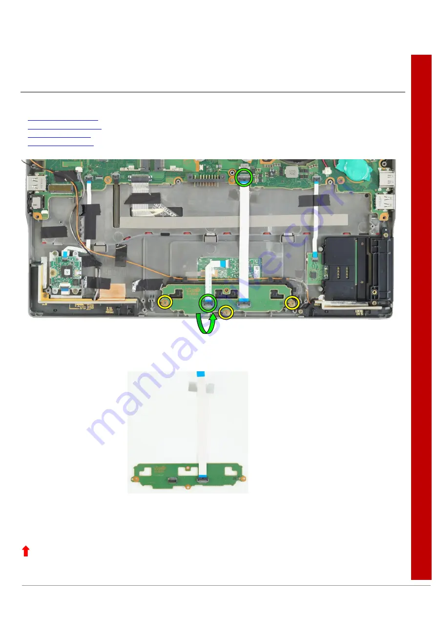
Removing the Touchpad buttons sub board   

Required work steps: 


Switching off the battery


Removing the lower assy


Removing the battery


Removing the speaker


Required tools: 


Screwdriver: Phillips PH00 


► 

Open the connections (green circles) by flipping open the respective lock and remove the flexprint cables.   

► 

Loosen and remove the three screws M2XL2.5 (yellow circles). 

► 

Now the sub board touchpad buttons can be removed from the unit. 


  Return to Table of Contents 


Summary of Contents for LIFEBOOK U7411

Page 1: ...sub board 19 Removing the touchpad buttons 20 Removing the fan 21 Removing the heatsink 22 Fingerprint sensor incl SecureBio sub board 23 Removing the CMOS battery 24 Removing the TPM module 25 Removing the keyboard 26 Inserting the red plastic strip of the keyboard 28 Removing the mainboard 29 Removing the upper assy of the case 30 Removing the LCD assy 32 Removing the LCD hinge covers 33 Removin...

Page 2: ...e opening the device After unplugging the mains plug discharge the remaining voltage by pressing the activation button Remove all externally connected cables Take care not to pinch any cables when installing removing components Please ensure that the installed components that might heat up intensely during operation do not exceed the permitted operating temperature Please take note of the target a...

Page 3: ... use items with sharp edges screwdrivers to lever them out Parts with Electrostatic Sensitive Devices ESD can be identified by a corresponding label When dealing with boards with ESDs the following points must always be observed Always ensure there is a static discharge e g by touching a grounded object prior to commencing with the work The devices and tools being used must not be statically charg...

Page 4: ...5XL3 D4 5 Screwdriver Phillips PH00 Screw M2 5XL4 Screwdriver Phillips PH00 Screw M2 5XL6 D4 5 Screwdriver Phillips PH00 Screw M2XL2 5 Screwdriver Phillips PH00 Screw M3XL3 5 1 Screwdriver Phillips PH00 Return to Table of Contents ...

Page 5: ...Page 5 of 49 Tools Screwdriver Phillips PH00 Plastic tool Plastic tool Return to Table of Contents ...

Page 6: ... lay an anti slip cloth on this surface to prevent the notebook from being scratched Push a pen or piece of wire e g a paper clip into the opening of the battery reset button yellow arrow to disconnect the battery from the system Warning The battery can be disconnected by pushing the battery reset button located on the bottom of the device As soon as an AC adapter is connected to the device the ba...

Page 7: ...frame Figure 1 Figure 2 Figure 3 Open the SIM card cover Figure 1 The SIM card cover is embedded in the device Carefully pull the SIM card cover out of the opening with your thumb and index finger until it can be removed completely Figure 2 The SIM card cover can now be removed Figure 3 Return to Table of Contents ...

Page 8: ... is fed into the device and embedded there Figure 1 Slide the SIM card cover bracket into the SIM tray opening green arrow Figure 2 Check that the SIM card cover is correctly seated by pulling the cover forward out of the device The SIM card cover is correctly inserted if it cannot simply be pulled completely out of the device but remains in the device due to being embedded Figure 3 Return to Tabl...

Page 9: ...sembly SB M 10030 Minimum requirements to properly finalise hardware repairs on mobile systems SB M 15007 WIN8x WIN10 Spare product key for repaired devices For any information about ESD please refer to the web based training course ESD in electronics ...

Page 10: ... plug from the mains outlet Disconnect all the cables that are connected to the notebook Turn your notebook over and place it on a stable and flat surface If necessary place a non slip cloth on the surface to avoid scratching the notebook Remove the thirteen screws yellow circles Please note that the screws are not removed from the housing but remain on the lower assy Lift the lower assy from the ...

Page 11: ...ing off the battery Removing the lower assy Required tools Screwdriver Phillips PH00 Remove the six screws yellow circles Please note here that the screws are not removed from the battery but remain on the battery Now lift the battery out of the device as indicated by the green arrow Return to Table of Contents ...

Page 12: ... films are included in the scope of delivery when the mainboard is ordered and are fitted in the device after replacement of the mainboard To access the components such as memories WLAN module LTE module TPM module fan CMOS battery or heatsink fold the white protective films to the side or remove them very carefully These are fixed at points with double sided adhesive tape see red arrows After the...

Page 13: ...ff the battery Removing the lower assy Removing the battery Required tools Plastic tool Position of the memories red frame Using a plastic tool loosen the memories locks red circles by pushing them sideways yellow arrows Now the storage module can be pulled out of the socket green arrows Return to Table of Contents ...

Page 14: ...r fingerprint sensor M 2 modules in half size 22x30 are used In the SPI Spare Part Information tool these modules are marked with the suffix 2230 Devices that are configured without a palm vein sensor or fingerprint sensor are equipped with a full size module 22x80 Position of the M 2 module red frame Loosen and remove the screw M2XL2 5 yellow circle After removing the screw the M 2 module flicks ...

Page 15: ... the battery Required tools Screwdriver Phillips PH00 Plastic tool Position of the LTE module red frame Loosen and remove the screw M2XL2 5 yellow circle Carefully pull both WWAN antennas from the LTE module red circles To do so use a suitable plastic tool Now the LTE module is loose and can be carefully pulled out of the socket in the direction of the green arrow ...

Page 16: ...vice technicians Warning When fitting the LTE module make sure that both antenna cables are properly connected The yellow cable must be connected to the MAIN port and the orange one to the AUX port yellow MAIN orange AUX Return to Table of Contents ...

Page 17: ...s therefore not replaceable In case of repair in connection with the WLAN module the mainboard must therefore be replaced Position of the WLAN module red frame Carefully pull the two WLAN antennas upwards off the WLAN module red circles To do so use a suitable plastic tool Warning Please ensure that the two WLAN antenna cables are connected correctly The grey cable must be connected to the MAIN po...

Page 18: ... of the socket downwards yellow arrow Carefully remove the black adhesive tapes red arrows that hold the cable of the speaker The speaker is fixed in the device by plastic latches yellow circles it is not screwed The speaker can now be removed upwards from the device green arrow Warning When removing the speaker make sure that the two rubber rings on the left and right of the loudspeaker are seate...

Page 19: ...ing the lower assy Removing the battery Removing the speaker Required tools Screwdriver Phillips PH00 Open the connections green circles by flipping open the respective lock and remove the flexprint cables Loosen and remove the three screws M2XL2 5 yellow circles Now the sub board touchpad buttons can be removed from the unit Return to Table of Contents ...

Page 20: ...hing off the battery Removing the lower assy Removing the battery Removing the speaker Removing the touchpad buttons sub board Required tools Plastic tool Remove the orange antenna cable from the guides on the touchpad cover red arrows You can then remove the touchpad buttons from the device Return to Table of Contents ...

Page 21: ...ssy Removing the battery Required tools Screwdriver Phillips PH00 Plastic tool Loosen and remove the two screws M2XL2 5 yellow circles Carefully pull the fan cable red frame out of the socket in the direction of the green arrow Use a suitable plastic tool if necessary Now the fan can be lifted up and out of the device Return to Table of Contents ...

Page 22: ...e heatsink is bent or otherwise damaged the heat sink can also be replaced individually Remove the four screws SCRM2 HSK yellow circles Lift the heatsink and remove it green arrow A thermal grease is applied between the mainboard and the heatsink red lightning symbol This may have to be replaced if the heatsink is replaced This must be considered when ordering the heatsink The item numbers of the ...

Page 23: ...ound under Spare Part Information tool The fingerprint sensor together with or without SecureBio sub board is part of the upper assy This is not replaced individually In case of repair the corresponding upper assy of the case must therefore be ordered and replaced Designations of upper assys of the case with fingerprint sensor in SPI Spare Part Information UPPER ASSY W SC W FP 4G UPPER ASSY W SC W...

Page 24: ...g the lower assy Removing the battery Required tools Plastic tool Carefully pull the cable from the CMOS battery red frame out of the socket towards the green arrow Use a suitable plastic tool if necessary Now the CMOS battery can be removed This is glued on with double sided adhesive tape and can be easily removed Return to Table of Contents ...

Page 25: ...ork steps Switching off the battery Removing the lower assy Removing the battery Required tools Screwdriver Phillips PH00 Position of the TPM module red frame Loosen and remove the screw M2XL2 5 yellow circle Now you can remove the TPM module from the device green arrow Return to Table of Contents ...

Page 26: ...ard yellow circle outwards slightly out of the device This is necessary for getting a better grip of the plastic strip from the other side of the device Then carefully turn the device over Make sure that nothing falls out of the device Open the device Carefully remove the red plastic strip below the keyboard using a suitable plastic tool Do this by gripping the right side under the plastic strip w...

Page 27: ...Page 27 of 49 Only intended for authorised service technicians Slide the keyboard down yellow arrows and then remove it from the case green arrow Return to Table of Contents ...

Page 28: ...tic tool Figure 1 Figure 2 Figure 3 Slide the red plastic strip on the left side of the keyboard into the openings provided as shown in Figure 1 Then push the plastic strip to the left until it stops under the keyboard Figure 2 Now insert the plastic strip on the right hand side of the keyboard into the opening on the far right and then carefully press it down until it snaps completely into place ...

Page 29: ...orehand These components must be reconnected to the new mainboard after the mainboard has been replaced Loosen and remove the five M2XL2 5 screws yellow circles Open the connectors red circles red ovals and remove the cables from the mainboard Now the mainboard can be removed from the device Warning There are white protective foils in the upper part of the device see section Removing the white pro...

Page 30: ...speaker Removing the mainboard Removing the touchpad buttons sub board Removing the touchpad buttons Required tools Screwdriver Phillips PH00 Plastic tool Perform all necessary work steps as described Remove the six M2 5XL4 B screws yellow circles that fix the hinges Carefully open the device a little so that the hinges can be slightly opened green arrows Then carefully disconnect the upper assy f...

Page 31: ...tions of upper assys in the case in the SPI Spare Part Information UPPER ASSY W SC 4G UPPER ASSY W SC W FP 4G UPPER ASSY W SC W FP SEC BIO 4G UPPER ASSY W SC W PV 4G UPPER ASSY WO SC W FP 4G UPPER ASSY WO SC W FP 5G UPPER ASSY WO SC W FP SEC BIO4G UPPER ASSY WO SC W FP SEC BIO 5G UPPER ASSY W O SC W PV 4G UPPER ASSY W O SC W PV 5G UPPER ASSY W O SC W O PV FP 4G UPPER ASSY W O SC W O PV FP 5G Retur...

Page 32: ...e cable upwards red oval Disconnect the WLAN antennas blue circles from the WLAN module Disconnect the connector green oval from the mainboard Then remove the six M2 5XL4 B screws yellow circles that hold the hinges Carefully open the device a little so that the hinges can be slightly opened green arrows Then carefully disconnect the upper assy from the LCD assy by carefully pulling the upper assy...

Page 33: ...nicians Removing the LCD hinge covers Required work steps Switching off the battery Removing the lower assy Removing the battery Removing the LCD assy Required tools none Remove the hinge covers by carefully pulling them upwards Return to Table of Contents ...

Page 34: ... Removing the hinge covers Required tools Plastic tool Use a plastic tool to disconnect the LCD back cover assy from the LCD front cover assy For example start at the right side and move very carefully with the plastic tool around the LCD assy towards the arrow yellow arrows Warning The frame of the LCD back cover assy is very thin Be especially careful while disconnecting the screen covers to avo...

Page 35: ...rvice technicians Warning After removing the LCD back cover assy be sure to look for the two small rubber covers of the camera which is located in the LCD front cover assy red frame These are loosely attached to the camera and can easily fall off ...

Page 36: ... assy Removing the battery Removing the LCD assy Required tools Screwdriver Phillips PH00 Open the hinges at an angle of approx 90 degrees so that the screws of the hinges are easily accessible Loosen and remove the two M2 5 L2 5 screws yellow circles and the two M2 5XL5 1 B screws red circles Now the hinges can be removed Return to Table of Contents ...

Page 37: ...e LCD back cover assy Removing the hinge covers Required tools Screwdriver Phillips PH00 To remove the LCD panel loosen and remove the two screws M2XL2 5 0 yellow circles The LCD panel can now be carefully removed from the LCD front cover assy Warning Be very careful when disconnecting the LCD panel from the LCD front cover assy it is connected to the lower screen cover by the LCD cable flash see ...

Page 38: ...he retaining clip and then carefully pull the cable towards the yellow arrow The LCD panel is now completely separated from the LCD front cover assy The LCD front cover assy is available in different variants depending on the configuration You can find the correct part numbers in the SPI Spare Part Information tool Return to Table of Contents ...

Page 39: ...configuration x x Cooling 13 Heatsink x 176 Fans x 10 Mainboard Depending on the device configuration x x x 71 LTE module Depending on the device configuration x 24 TPM module x 60 LCD display Depending on the device configuration x x 130 Keyboard Depending on the device configuration x x 12 CMOS battery x 190 Speaker x 156 Touchpad buttons Cover TP buttons x 20 Touchpad buttons sub board x Cables...

Page 40: ...Page 40 of 49 ...

Page 41: ...Page 41 of 49 ...

Page 42: ...Page 42 of 49 ...

Page 43: ...Page 43 of 49 ...

Page 44: ...Page 44 of 49 ...

Page 45: ...Page 45 of 49 ...

Page 46: ...Page 46 of 49 ...

Page 47: ...Page 47 of 49 ...

Page 48: ...thod of attchment Detachable How to remove Open the cover Special tool for removal None 1 Lithium button batteries CR2032 Included on the mainboard 1 Components containing mercury Not contained Liquid crystal displays if applicable together with the casing with a surface area greater than 100 square centimetres and backlit displays with gas discharge lamps 100cm2 display Not contained Gas discharg...

Page 49: ...omatic Brominated compounds excluding Brominated diphenyl ether and biphenyls 17 aromatic Brominated compounds excluding Brominated diphenyl ether and biphenyls in combination with antimony compounds 22 aliphatic alicyclic chlorinated and Brominated compounds 42 Brominated organic phosphorus compounds Plastics parts weighing less than 25 grams may or may not contain brominated flame retardants The...

Reviews: