background image

1

P r e f a c e

Preface

ABOUT THIS GUIDE

This manual explains how to operate your LifeBook 
notebook’s hardware and built-in system software. Your 
notebook is compatible with the IBM® PC AT. 

It comes with Microsoft Windows® 2000, Windows XP 
Home, or Windows XP Pro pre-installed.

The LifeBook P Series notebook is a completely self-
contained unit with an active-matrix (TFT) color LCD 
display with touch screen capabilities. It has a powerful 
interface that enables it to support a variety of optional 
features. 

Conventions Used in the Guide

Keyboard keys appear in brackets. 
Example: [Fn], [F1], [ESC], [ENTER] and [CTRL].

Pages with additional information about a specific topic 
are cross-referenced within the text.
Example: (See page xx.)

On screen buttons or menu items appear in bold
Example: Click 

OK 

to restart your LifeBook notebook.

DOS commands you enter appear in Courier type. 
Example:

Shutdown the computer?

FUJITSU CONTACT INFORMATION

Service and Support

You can contact Fujitsu Service and Support in the 
following ways:

n

Toll free: 1-800-8Fujitsu (1-800-838-5487)

n

Fax: 1-901-259-5700 

n

E-mail: [email protected] 

n

Web site: http://www.fujitsupc.com

Before you place the call, you should have the 
following information ready so that the customer 
support representative can provide you with the
fastest possible solution:

n

Product name

n

Product configuration number

n

Product serial number

n

Purchase date

n

Conditions under which the problem occurred

n

Any error messages that have occurred

n

Hardware configuration

n

Type of device connected, if any

Fujitsu Online

You can go directly to the online Fujitsu Product catalog 
for your LifeBook notebook by clicking on the LifeBook 
Accessories Web site URL link, located in the Windows 
Start menu.

You can also reach Fujitsu Service and Support online by 
clicking on the Fujitsu Service and Support Web site 
URL link, located in the Service and Support Software 
folder of the Windows Start menu.

WARRANTY

Your LifeBook notebook is backed by a three- or one- 
year International Limited Warranty. Check the service 
kit that came with your notebook for warranty terms 
and conditions.

P O I N T

The point icon highlights information that will enhance 
your understanding of the subject material.

C A U T I O N

The caution icon highlights information that is 
important to the effective operation of your computer, 
or to the integrity of your files. Please read all caution 
information carefully.

W A R N I N G

The warning icon highlights information that can be 
hazardous to you, your LifeBook notebook, or your 
files. Please read all warning information carefully.

P O I N T

You must have an active internet connection to
use the online URL links.

B5FH-5961-01EN-00.book Page 1 Monday, April 29, 2002 2:58 PM

Summary of Contents for Lifebook P1110

Page 1: ...Quest Corporation SigmaTel is a registered trademark of SigmaTel Inc Rage Mobility M is a trademark of ATI Technologies Inc McAfee is a registered trademark of Network Associates McAfee com Inc All other trademarks mentioned herein are the property of their respective owners Copyright 2002 Fujitsu PC Corporation All rights reserved No part of this publication may be copied reproduced or translated...

Page 2: ...L i f e B o o k P 1 0 0 0 N o t e b o o k B5FH 5961 01EN 00 book Page 2 Monday April 29 2002 2 58 PM ...

Page 3: ...board Using the Keyboard 13 Numeric Keypad 13 Windows Key 13 Cursor Keys 13 Function Keys 14 Quick Point Pointing Device Clicking 15 Double Clicking 15 Dragging 15 Quick Point Device Control Adjustment 16 Touch Screen 16 Volume Control Controlling the Volume 18 3 GETTING STARTED Power Sources Connecting the Power Adapters 21 Display Panel Opening the Display Panel 22 Adjusting Display Panel Bright...

Page 4: ...e Special Edition DISE 49 6 CARE AND MAINTENANCE Care and Maintenance Batteries 54 Floppy Disks and Drives 54 PC Cards 54 7 SPECIFICATIONS Specifications Configuration Label 57 Microprocessor 57 Memory 57 Video 57 Audio 57 Mass Storage Device Options 57 Features 57 Device Ports 58 Keyboard 58 Dimensions and Weight 58 Power 58 Environmental Requirements 58 Popular Accessories 58 Pre Installed Softw...

Page 5: ...1 Preface B5FH 5961 01EN 00 book Page 1 Monday April 29 2002 2 58 PM ...

Page 6: ...L i f e B o o k P 1 0 0 0 N o t e b o o k B5FH 5961 01EN 00 book Page 2 Monday April 29 2002 2 58 PM ...

Page 7: ...ide you with the fastest possible solution n Product name n Product configuration number n Product serial number n Purchase date n Conditions under which the problem occurred n Any error messages that have occurred n Hardware configuration n Type of device connected if any Fujitsu Online You can go directly to the online Fujitsu Product catalog for your LifeBook notebook by clicking on the LifeBoo...

Page 8: ...2 L i f e B o o k P 1 0 0 0 N o t e b o o k S e c t i o n O n e B5FH 5961 01EN 00 book Page 2 Monday April 29 2002 2 58 PM ...

Page 9: ...3 2 Getting to Know Your LifeBook Notebook B5FH 5961 01EN 00 book Page 3 Monday April 29 2002 2 58 PM ...

Page 10: ...4 L i f e B o o k P 1 0 0 0 N o t e b o o k S e c t i o n T w o B5FH 5961 01EN 00 book Page 4 Monday April 29 2002 2 58 PM ...

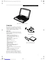
Page 11: ...ive Figure 2 3 n Lithium ion battery n Phone Modem RJ 11 telephone cable n Mini VGA cable n Two additional pointer caps n Stylus n Driver and Application Restore CD n Getting Started Guide n LifeBook User s Guide n International Limited Warranty Brochure n Microsoft Works CD Windows XP Home model only n Certification of Authenticity with operating system manual n Premium Care registration card and...

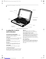
Page 12: ...tons and one cursor control button See Quick Point Pointing Device on page 15 for more information Keyboard A full size keyboard with dedicated Windows keys See Keyboard on page 13 for more information Suspend Resume Power On Button The Suspend Resume Power On button allows you to suspend notebook activity without powering off resume your LifeBook notebook from suspend mode and power on your noteb...

Page 13: ... LAN models only The Wireless LAN On Off Switch turns the wireless LAN device on and off Wireless LAN Antenna On wireless LAN models only The Wireless LAN Antenna is located behind the cover It is used for establishing communications with other wireless devices Wireless LAN On Off Switch on wireless LAN models only OFF Position ON Position Wireless LAN Antenna on wireless LAN models only B5FH 5961...

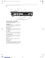
Page 14: ...r more information PC Card Slot The PC Card Slot allows you to install one Type II PC Card See PC Cards on page 34 for more information PC Card Eject Button The PC Card eject button allows you to remove PC Cards from the PC Card slot See PC Cards on page 34 for more information Air Vents The air vents allow for proper cooling of the system while it is operating DC Power Jack The DC power jack allo...

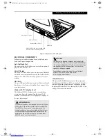
Page 15: ... Fast Ethernet 10 100 Base TX connection This jack is not included with systems that are configured with an Integrated Wireless LAN See Internal LAN RJ 45 Jack on page 35 for more information USB Ports LAN RJ 45 Jack not included with Modem RJ 11 Jack Mini VGA Jack Anti Theft Lock Slot Wireless LAN configured system W A R N I N G The internal modem is not intended for use with Digital PBX systems ...

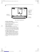
Page 16: ...r swapping a discharged battery with a charged Lithium ion battery See Lithium ion Battery on page 31 for more information Main Unit and Configuration Label The configuration label shows the model number and other information about your LifeBook notebook In addition the configuration portion of the label has the serial number and manufacturer information that you will need to give your support rep...

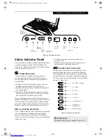
Page 17: ...e shut down from Windows but have not turned off the power switch AC ADAPTER INDICATOR The AC Adapter indicator states whether your notebook is operating from the AC adapter the Auto Airline adapter or the batteries This icon has two different states that can tell you what power source your LifeBook notebook is using On This means that either of the adapters are currently in use Off Power is only ...

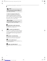
Page 18: ...rd The indicator will flash if your software tries to access a PC Card even if there is no card installed See PC Cards on page 34 for more information NUMERIC LOCK INDICATOR The Numeric Lock indicator states that the internal keyboard is set in ten key numeric keypad mode CAPS LOCK INDICATOR The Caps Lock indicator states that your keyboard is set to type in all capital letters SCROLL LOCK INDICAT...

Page 19: ...en Start menu button NUMERIC KEYPAD Certain keys on the keyboard perform dual functions as both standard character keys and numeric keypad keys NumLk can be activated by pressing the NumLk keys Turning off the NumLk feature is done the same way Once this feature is activated you can enter numerals 0 through 9 perform addition subtraction multiplication or division and enter decimal points using th...

Page 20: ... display When it is enabled displays with less than 1024 x 600 pixel resolution will still cover the entire screen n Fn F6 Pressing F6 repeatedly while holding Fn will lower the brightness of your display n Fn F7 Pressing F7 repeatedly while holding Fn will increase the brightness of the display n Fn F8 Pressing F8 repeatedly while holding Fn will decrease the volume of your LifeBook note book n F...

Page 21: ...releasing a button To left click move the cursor to the item you wish to select press the left button once and then immediately release it To right click move the cursor to the item you wish to select press the bottom button once and then imme diately release it Figure 2 13 Figure 2 13 Clicking DOUBLE CLICKING Double clicking means pushing and releasing the left button twice in rapid succession Th...

Page 22: ...erform the left click operation by tapping lightly with your finger on the Touch Screen once Figure 2 17 To right click go to Start Programs Fujitsu Touch Panel From that window you can specify a right button tool by using the Touch Panel Configuration Control button prior to the desired right mouse click It can be used two ways by holding down the key or by pressing the key once Figure 2 17 Click...

Page 23: ...on Utility before you use the Touch Screen for the first time or after you change the display resolution To run the calibration utility 1 On the Start menu point to Programs or All Programs in Windows XP Point to Fujitsu Touch Panel Compensation Tool This will open the Compensation Tool 2 Adjust the display of your notebook to a comfortable angle and find the red symbol in the upper left corner of...

Page 24: ...Certain external audio devices you might connect to your system may have hardware volume controls Each source discussed above puts an upper limit on the volume level that must then be followed by the other sources We recommend that you experiment with the various volume controls to discover the optimal sound level P O I N T Any software that contains audio files will also contain a volume control ...

Page 25: ...19 3 Getting Started B5FH 5961 01EN 00 book Page 19 Monday April 29 2002 2 58 PM ...

Page 26: ...20 L i f e B o o k P 1 0 0 0 N o t e b o o k S e c t i o n T h r e e B5FH 5961 01EN 00 book Page 20 Monday April 29 2002 2 58 PM ...

Page 27: ... 3 1 Connecting the Optional Auto Airline Adapter 1 Plug the DC cable into the DC power jack on your notebook 2 Plug the Auto Airline adapter into the cigarette lighter of an automobile with the ignition key in the On or Accessories position OR 3 Plug the Auto Airline adapter into the DC power jack on an airplane seat Switching from AC Adapter Power or the Auto Airline Adapter to Battery Power 1 B...

Page 28: ...ing repeatedly will lower the brightness of your display Fn F7 Pressing repeatedly will increase the brightness of the display Using the Power Management Utility Windows 2000 only Adjusting the brightness using the Power Management changes the setting permanently 1 Double click the Battery icon in the lower right corner of your display This will open the BatteryAid Properties dialog box 2 Select t...

Page 29: ...e BIOS Setup Utility the system displays the operating system s opening screen The boot sequence is executed when You turn on the power to your LifeBook notebook You restart your notebook from the Windows Shut Down dialog box The software initiates a system restart Example When you install a new application You reset the system by pressing the three keys CTRL ALT DEL BIOS SETUP UTILITY The BIOS Se...

Page 30: ...ition of Use page Windows Registration If your connection is successful you will go to a Registration Confirmation page Enter the requested information then check the box at the bottom to register your copy of Windows with Microsoft Once you have finished click the Next button to continue Final Settings The first part of your final settings is the Windows End User License Agreement Read the agreem...

Page 31: ...e power is off or your notebook is in Hibernation mode STANDBY MODE Standby or Suspend to RAM mode in Windows saves the contents of your LifeBook notebook s system memory during periods of inactivity by maintaining power to critical parts This mode will turn off the CPU the display the hard drive and all of the other internal components except those necessary to maintain system memory and allow fo...

Page 32: ...n the Windows Control Panel allows you to configure some of the power management settings For example you can use the Power Management to set the timeout values for turning off the display and hard disks whether you are running the notebook on battery power or one of the adapters The settings may also be changed in the BIOS RESTARTING THE SYSTEM If your system is on and you need to restart it be s...

Page 33: ...ion from within the Windows Shut Down dialog box 3 Click OK to shut down your notebook If you are going to store your notebook for a month or more see Care and Maintenance Section C A U T I O N Be sure to close all files exit all applications and shut down your operating system prior to turning off the power If files are open when you turn the power off you will lose any changes that have not been...

Page 34: ...28 L i f e B o o k P 1 0 0 0 N o t e b o o k S e c t i o n T h r e e B5FH 5961 01EN 00 book Page 28 Monday April 29 2002 2 58 PM ...

Page 35: ...29 4 User Installable Features B5FH 5961 01EN 00 book Page 29 Monday April 29 2002 2 58 PM ...

Page 36: ...30 L i f e B o o k P 1 0 0 0 N o t e b o o k S e c t i o n F o u r B5FH 5961 01EN 00 book Page 30 Monday April 29 2002 2 58 PM ...

Page 37: ...w battery message the batteries will continue to discharge until they are too low to operate When this happens your notebook will go into Suspend mode Your data will be automatically saved to your hard disk drive just prior to entering Suspend mode P O I N T S Actual battery life will vary based on screen bright ness applications features power management set tings battery condition and other cust...

Page 38: ...ered down warm swapping means changing the battery while the system is being powered with another method such as an AC Adapter Cold swapping Batteries To cold swap batteries in your battery bay follow these easy steps Figure 4 1 1 Have a charged battery ready to install 2 Shut down your notebook 3 Slide the battery bay release buttons to open the bay 4 Remove the battery from the bay 5 Slide the n...

Page 39: ... need to format new disks unless they are preformatted Please refer to your operating system manual for step by step instructions on formatting a disk To prevent accidental erasure of the data stored on a disk slide the write protect tab until a small hole is exposed This sets the disk into a protected state where nothing can be added or removed If you want to add or remove data on a protected dis...

Page 40: ...DS To remove a PC Card follow these easy steps 1 See your PC Card manual for specific instructions on removing your card Some PC Cards may require your notebook to be in Suspend Mode or Off while removing them 2 Push the Eject button in until it is flush with the notebook This will push the PC Card slightly out of the slot allowing you to remove the card Eject Button PC Card Slot PC Card W A R N I...

Page 41: ... is seated HEADPHONE JACK The headphone jack allows you to connect headphones or powered external speakers to your notebook Your headphones or speakers must be equipped with a 1 8 3 5 mm stereo mini plug In order to connect head phones or speakers follow these easy steps See figure 2 6 on page 8 for location 1 Align the connector with the port opening 2 Push the connector into the port until it is...

Page 42: ...ou to change your selection of where to send your display video Each time you press the key combination you will step to the next choice starting with the built in display panel only moving to the external monitor only finally moving to both the built in display panel and an external monitor B5FH 5961 01EN 00 book Page 36 Monday April 29 2002 2 58 PM ...

Page 43: ...37 5 Troubleshooting B5FH 5961 01EN 00 book Page 37 Monday April 29 2002 2 58 PM ...

Page 44: ...38 L i f e B o o k P 1 0 0 0 N o t e b o o k S e c t i o n F i v e B5FH 5961 01EN 00 book Page 38 Monday April 29 2002 2 58 PM ...

Page 45: ...thus eliminating them as possible causes of failure 5 Turn on your notebook Make sure it has been off at least 10 seconds before you turn it back on 6 Go through the boot sequence 7 If the problem has not been resolved refer to the Troubleshooting Table that follows for more detailed troubleshooting information 8 If you are still having problems after referring to the Troubleshooting Table go to t...

Page 46: ...y disk You tried to write to a write protected floppy disk Eject the floppy disk and set it to write enable See Preparing a Disk for Use on page 44 for more information Floppy disk is not loaded correctly Eject floppy disk check orientation and re insert See Ejecting a Disk on page 44 for more information The floppy disk drive may not be properly installed Remove and re install your floppy disk dr...

Page 47: ...Your Power On screen or Main menu of the BIOS setup utility information does not show the correct amount of installed memory Your memory upgrade module is not properly installed Remove and re install your memory upgrade module See Memory Upgrade Module on page 35 for more infor mation You have a memory failure Check for Power On Self Test POST messages See Power On Self Test Messages on page 47 fo...

Page 48: ...your LifeBook notebook and nothing seems to happen The installed primary battery is completely discharged there is no optional second battery installed or there is no Power adapter AC or Auto Airline installed Check the Status Indicator Panel to determine the pres ence and condition of the batteries See Status Indicator Panel on page 11 for more information Install a charged battery or a Power ada...

Page 49: ... installed batteries are dead Replace the battery with a charged one or install a Power adapter No batteries are installed Install a charged battery The batteries are improperly installed Verify that the batteries are properly connected by re installing them verify that the battery latches are properly seated Your installed batteries are faulty Verify the condition of the batteries using the Statu...

Page 50: ...rnal hard drive An error message is displayed on the screen during the notebook boot sequence Power On Self Test POST has detected a problem See the Power On Self Test POST messages to deter mine the meaning and severity of the problem Not all messages are errors some are simply status indicators See Power On Self Test Messages on page 47 for more information Your notebook appears to change setup ...

Page 51: ...cts from the keyboard The Built in Display has bright or dark spots If the spots are very tiny and few in number this is normal for a large LCD display This is normal do nothing If the spots are numerous or large enough to interfere with your operation needs Display is faulty contact your support representative The application display uses only a portion of your screen and is surrounded by a dark ...

Page 52: ...Specifications section See Specifications on page 57 for more information Miscellaneous Problems An error message is displayed on the screen during the operation of an appli cation Application software often has its own set of error message displays See your application manual and help displays screens for more information Not all messages are errors some may simply be status Problem Possible Caus...

Page 53: ... fault which might cause you to lose data if you continue Contact your support representative Incorrect Drive A type run SETUP Type of floppy drive A not correctly identified in Setup This means that the floppy disk drive type identified in your setup utility does not agree with the type detected by the Power On Self Test Run the setup utility to correct the inconsistency Incorrect Drive B type ru...

Page 54: ...d life of 2 to 3 years System BIOS shadowed System BIOS copied to shadow RAM System CMOS checksum bad run SETUP BIOS CMOS RAM has been corrupted or modified incorrectly perhaps by an application program that changes data stored in BIOS memory Run Setup and reconfigure the system System RAM Failed at offset nnnn System memory failed at offset nnnn of in the 64k block at which the error was detected...

Page 55: ... or NTFS partition and it must be directly before the backup partition on your hard disk 1 At the Drive Image Special Edition main screen click Options Create New Backup There is also a button on the main DISE screen that performs the same function 2 You will be prompted to type a password Type a password or leave the password fields blank then click OK DISE displays a warning that it must go to D...

Page 56: ...50 L i f e B o o k P 1 0 0 0 N o t e b o o k S e c t i o n F i v e B5FH 5961 01EN 00 book Page 50 Monday April 29 2002 2 58 PM ...

Page 57: ...51 6 Care and Maintenance B5FH 5961 01EN 00 book Page 51 Monday April 29 2002 2 58 PM ...

Page 58: ...52 L i f e B o o k P 1 0 0 0 N o t e b o o k S e c t i o n S i x B5FH 5961 01EN 00 book Page 52 Monday April 29 2002 2 58 PM ...

Page 59: ...otebook If storing your notebook for a month or longer turn your LifeBook notebook off fully charge all batteries and remove and store all Lithium ion batteries Store your notebook and batteries separately If you store your LifeBook with a battery installed the bat tery will discharge and battery life will be reduced In addition a faulty battery might damage your Life Book Store your Fujitsu LifeB...

Page 60: ...disk label Avoid storing the floppy disks in extremely hot or cold locations or in locations subject to severe temperature changes Store at temperatures between 50º F 10ºC and 125ºF 52ºC Do not touch the exposed part of the disk behind the metal shutter Caring for your Floppy Disk Drive To clean wipe the floppy disk drive clean with a dry soft cloth or with a soft cloth dampened with water or a so...

Page 61: ...55 7 Specifications B5FH 5961 01EN 00 book Page 55 Monday April 29 2002 2 58 PM ...

Page 62: ...56 L i f e B o o k P 1 0 0 0 N o t e b o o k S e c t i o n S e v e n B5FH 5961 01EN 00 book Page 56 Monday April 29 2002 2 58 PM ...

Page 63: ...s n Internal refresh rate 60 Hz n External 1280 x 1024 pixel resolution 64K colors Simultaneous Video Yes 1024 x 600 16M colors SXGA XGA SVGA and VGA compatible n Dual monitor support No Video RAM ATI Rage Mobility M with 4MB embedded Video RAM AUDIO n SigmaTel STAC9757T codec with 16 bit stereo audio n SigmaTel Surround Stereo Enhancement n Stereo headphone jack 200 mVrms 32 ohms 1 Vrms 10Kohms n...

Page 64: ...otebook Fujitsu Model FPCAC28AP which includes an AC cable Power Management Conforms to ACPI Advanced Configuration and Power Interface ENVIRONMENTAL REQUIREMENTS Temperature Operating 41 to 95 F 5 to 35 C Non operating 5 to 140 F 15 to 60 C Humidity Operating 20 to 85 relative non condensing Non operating 8 to 85 relative non condensing Altitude Operating 10 000 feet 3 048 m maximum POPULAR ACCES...

Page 65: ... tool that provides automated diagnosis and solutions for your hardware and software problems The FSA installer is pre loaded the full version is included on the Fujitsu Service Assistant CD New support information for the Fujitsu Service Assis tant tool may be available after the purchase of your notebook You should periodically connect to the Internet while using the Fujitsu Service Assistant to...

Page 66: ...60 L i f e B o o k P 1 0 0 0 N o t e b o o k S e c t i o n S e v e n B5FH 5961 01EN 00 book Page 60 Monday April 29 2002 2 58 PM ...

Page 67: ...61 8 Glossary B5FH 5961 01EN 00 book Page 61 Monday April 29 2002 2 58 PM ...

Page 68: ...62 L i f e B o o k P 1 0 0 0 N o t e b o o k S e c t i o n E i g h t B5FH 5961 01EN 00 book Page 62 Monday April 29 2002 2 58 PM ...

Page 69: ...s than your system RAM and used in specially structured ways to make your overall data handling time faster CardBus A faster 32 bit version of the PC Card interface which offers performance similar to the 32 bit PCI architecture CD ROM Compact disc read only memory This is a form of digital data storage which is read optically with a laser rather than a magnetic head A typical CD ROM can contain a...

Page 70: ... where the platter is very stiff Hexadecimal A decimal notation for the value of a 4 bit binary number 0 9 A B C D E F Example 2F in hexa decimal 00101111 in binary 47 in decimal I O Input Output Data entering and leaving your LifeBook notebook in electronic form I O Port The connector and associated control circuits for data entering and leaving your LifeBook notebook in elec tronic form IDE Inte...

Page 71: ...ur hardware what to do and how and when to do it PS 2 An IBM series of personal computers which established a number of standards for connecting external devices such as keyboards and monitors RAM Random Access Memory A hardware component of your LifeBook notebook that holds binary information both program and data as long as it has the proper power applied to it RAM Module A printed circuit card ...

Page 72: ...y of devices USB Universal Serial Bus An external bus standard that allows for fast data transfer A single USB port can be used to connect up to 127 peripheral devices such as mice modems and scanners VGA Video Graphics Array A video display standard originally introduced by IBM with the PS 2 series of personal computers Resolution of 600 x 480 pixels VRAM Video Random Access Memory A memory dedic...

Page 73: ...esult in failure to ring in response to an incoming call In most but not all areas the sum of the RENs of all of the devices should not exceed five 5 To be certain of the number of devices you may connect to your line as determined by the RENs contact your local telephone company If this equipment causes harm to the telephone network your telephone company may discontinue your service temporarily ...

Page 74: ...strement Le sigle IC placé devant le numéro d enregistrement signifie que l enregistrement s est effectué conformément à une déclaration de conformité et indique que les spécifications techniques d Industrie Canada ont été respectées Il n implique pas qu Industrie Canada a approuvé le matériel Avant de connecter cet équipement à une ligne télépho nique l utilisateur doit vérifier s il est permis d...

Page 75: ... N To reduce the risk of fire use only 26AWG or larger telecommunications line cord W A R N I N G S n For continued protection against risk of fire replace only with the same type and rating fuse n Danger of explosion if Lithium clock battery is incor rectly replaced Replace only with the same or equiva lent type recommended by the manufacturer Dispose of used batteries according to the manufactur...

Page 76: ...70 L i f e B o o k P 1 0 0 0 N o t e b o o k S e c t i o n E i g h t B5FH 5961 01EN 00 book Page 70 Monday April 29 2002 2 58 PM ...

Page 77: ...71 Appendix Integrated Wireless LAN User s Guide B5FH 5961 01EN 00 book Page 71 Monday April 29 2002 2 58 PM ...

Page 78: ...72 L i f e B o o k P 1 0 0 0 N o t e b o o k A p p e n d i x B5FH 5961 01EN 00 book Page 72 Monday April 29 2002 2 58 PM ...

Page 79: ...nterference Statement This equipment has been tested and found to comply with the limits for a Class B digital device pursuant to Part 15 of the FCC Rules These limits are designed to provide reasonable protection against harmful interfer ence in a residential installation This equipment gener ates uses and can radiate radio frequency energy If not installed and used in accordance with the instruc...

Page 80: ...AdHoc mode you can use the function supported by Microsoft Network such as File and Print Sharing to exchange files and share a printer or other peripheral devices To use the AdHoc Mode you must set the same SSID and the same encryption key for all the computers that are connected All connected computers can communi cate with each other within the communication range Infrastructure Mode If a numbe...

Page 81: ... access point refer to the access point manual P O I N T When you receive your LifeBook the integrated wireless LAN device and drivers have already been installed This procedure outlines the steps for setting the device parameters Updated drivers and or utilities may become available after this manual is printed see any addenda or fliers that may be included in the system packaging Item Descriptio...

Page 82: ...is case Create keys with Passphrase and subsequent items are greyed out and you cannot enter anything 40 bit The encryption is set Select either Create keys with Passphrase Create keys manu ally or ASCII Input and enter the encryption keys 104 bit The encryption is set Select either Create keys with Passphrase Create keys manu ally or ASCII Input and enter the encryption keys Create Keys with Pass...

Page 83: ...he following example shows how to set sharing the Work folder on the c drive 1 Double click My Computer C drive on the desktop 2 Right click the Work folder then click Sharing from the menu that appears The Work Properties window appears 3 Click Sharing and select items as specified below Table 6 Password Setup 4 Click OK The folder is set for sharing and the Work folder icon changes P O I N T If ...

Page 84: ...ection describes how to set the network connection for a computer with Windows 2000 Network Settings In this section you set TCP IP Settings and complete Checking Computer Name and Workgroup required for the network connection TCP IP Settings 1 Click Start Settings Control Panel Item Description Not Shared Disables printer sharing Shared as Enables printer sharing Share Name Specifies a share name...

Page 85: ...onnections icon The Network and Dial up Connections windows appears 3 Right click the Local Area Connection then click Properties from the menu that appears Local Area Connection Properties appears P O I N T More than one network adapter is installed in your system if more than one Local Area Connection entry is displayed In this case select the Local Area Connection entry with Intersil PRISM Wire...

Page 86: ...ring 4 Click OK The printer sharing is set and the icon changes Checking the Connection After the network setting is completed access the shared drive on another computer to check the connectivity of the wireless LAN network Accessing Another Computer 1 Double click the My Network Places icon on the desktop My Network Places appears 2 Double click Computers near me The computers that are connected...

Page 87: ...he access point For how to check the encryption keys set for the access point refer to the manual supplied with the access point Item Description State Shows the current condition of connection The MAC address of the other computer to which you are connected is displayed when the connection is successful If you are connected to more than one computer the computer that has the best connectivity is ...

Page 88: ...work Specify the same name as that specified on the access point that is to be connected For access point instructions refer to the manual that comes with the access point Key Format Click the down arrow and select the input for the Network key ASCII characters Select this when using ASCII characters for the Network Key Characters that can be used follow 0 9 A Z a z and _ underscore Example To set...

Page 89: ...etworks is added to the list 7 Click Close Sharing Files The following example shows how to set sharing the Work folder on the c drive 1 Click Start My Computer 2 Double click the Local Disk c icon 3 Right click the Work folder and then click Sharing and Security from the menu that appears Work Properties appears 4 Click If you understand the security risks but want to share files without running ...

Page 90: ...e drive to which you want to connect The contents of the drive will appear and is available for use If you have a question or problem refer to Trouble shooting Table on page 85 Checking the Connectivity 1 Click Start Control Panel 2 Double click the PRISM Settings icon PRISM Wireless Setting appears 3 Check the connectivity on the Link tab The current condition of connection is displayed Table 17 ...

Page 91: ...e and password is registered in the computer The network has not been set up correctly Check the setting for the protocol workgroup and sharing To check this you need a different procedure depending upon the operating system that you use Refer to the appropriate section of this chapter It takes time before the network is searched and the computer connected is displayed Perform the following steps ...

Page 92: ...ams Accessories Command Prompt Windows XP Click Start All Programs Accessories Command Prompt 2 Enter IPCONFIG command and press Enter If your hard disk is C drive enter C ipconfig Check that the IP address is correctly displayed under the IP Address Example IP address 10 0 1 3 Subnet Mask 255 255 255 0 Default Gateway 10 0 1 1 No communication due to poor radio signal Shorten the distance between...

Page 93: ...imilar to below 5 To check that your system is communicating with other systems go to the DOS prompt and type ping XXX XXX XXX XXX With the destination IP address in place of XXX XXX XXX XXX Example if the destination IP address is 10 0 1 3 C ping 10 0 1 3 A message similar to the following appears if the connection is successful Pinging 10 0 1 3 with 32 bytes of data Reply from 10 0 1 3 bytes 32 ...

Page 94: ...emoval appears 5 Click OK The device is removed and System Settings Change appears 6 Click No 7 Close System Properties 8 Make sure that the icon has disappeared from the task tray in the lower right corner of the screen 9 Click Start Settings Control Panel Control Panel appears 10 Double click Add Remove Programs Add Remove Programs Properties appears 11 Double click PRISM 11Mbps Wireless LAN for...

Page 95: ...lick Uninstall from the menu that is displayed Confirm Device Removal appears 6 Click OK 7 Close System Properties 8 Make sure that the icon has disappeared from the task tray in the lower right corner of the screen 9 Click Start Settings Control Panel 10 Double click Add Remove Programs Add Remove Programs appears 11 Perform the following steps Click PRISM 11Mbps Wireless LAN for Windows Click Ch...

Page 96: ...AN PCI Card and click Uninstall from the menu that is displayed Confirm Device Removal appears 6 Click OK 7 Close System Properties 8 Make sure that the icon has disappeared from the task tray in the lower right corner of the screen 9 Click Start Control Panel Control Panel appears 10 Double click Add Remove Programs Add Remove Programs appears 11 Perform the following steps Click PRISM 11Mbps Wir...

Page 97: ...SES Setting IP Addresses If you are not sure how to set the IP address refer to the following procedure If you have an access point DHCP server on the network set the IP address as follows Windows 98 Obtain an IP address automatically Windows 2000 Obtain an IP address automatically Windows XP Obtain an IP address automatically If the IP address is already assigned to the computer in the network as...

Page 98: ...11 5 5 2 1Mbps auto change Frequency Range 2 400 2 473 MHz Channels One of 11 channels is used Card Type Non intelligent VCC Class B Security Network name encryption key Supported Operating Systems Windows 98 Windows 2000 Windows XP Power Current Max 350mA Maximum number of units recommended for wireless LAN AdHoc network 10 or less B5FH 5961 01EN 00 book Page 92 Monday April 29 2002 2 58 PM ...
Page 99: ...3 CapsLock 12 Click Me 24 Closed Cover Switch 6 Cold swapping 32 Configuration Label 10 Contact Information 1 cursor control button 6 Cursor Keys 13 D DC Output Cable 21 DC Power Jack 8 21 DC power jack 8 Device Ports 35 DISE 49 Disk care 54 Display Panel 6 22 adjusting 22 brightness 22 closing 22 opening 22 power management 22 problems 44 45 Display Timeout 26 Drive Image Special Edition 49 Drive...

Page 100: ...icrophone Jack 8 35 Mini VGA Port 35 Modem 9 problems 41 Modem Jack 35 Modem Result Codes 48 Mouse problems 40 N Numeric Keypad 13 NumLk 12 O Optical Digital Audio Out Jack 9 P PC Card access indicator 12 care 54 installing 34 problems 42 removing 34 slot 8 PC Card Eject Lock Button 8 POST 65 Power 23 AC adapter 21 Auto Airline adapter 21 failure 42 indicator 11 management 25 off 26 problems 44 po...

Page 101: ...icking 16 double clicking 16 dragging 16 Troubleshooting 39 40 U Universal Serial Bus Port 35 USB 35 port 8 problems 41 42 USB Ports 9 V Volume 18 W Warm swap 32 Warranty 1 Windows end user license agreement 24 Windows keys 13 Wireless LAN 74 about IP addresses 91 before using 74 connecting Windows 98 2000 75 Connecting Windows XP Systems 81 if a Second LAN Device is Installed 91 modes 74 Network ...

Page 102: ...96 L i f e B o o k P 1 0 0 0 N o t e b o o k B5FH 5961 01EN 00 book Page 96 Monday April 29 2002 2 58 PM ...
Reviews: