background image

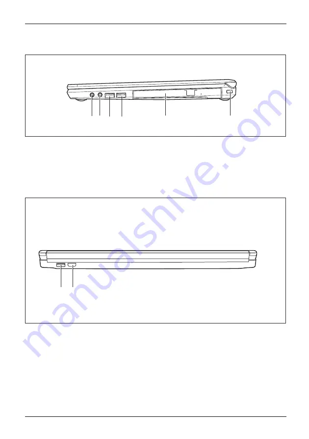
Ports and controls

Right side

1 2

3

4

5

6

1 = Headphone port
2 = Microphone port
3 = USB port 3.0
4 = USB 3.0 port with charging function

(Anytime USB charge)

5 = Modular bay with optical drive or second

battery, second HDD or Weight Saver
(depending on con

fi

guration)

6 = Security Lock device

Rear

1

2

1 = USB port 2.0 (LIFEBOOK E746/E756 only)

2 = HDMI port (LIFEBOOK E756 only)

Fujitsu

15

Summary of Contents for lifebook e736

Page 1: ...System Operating Manual FUJITSU LIFEBOOK E736 FUJITSU LIFEBOOK E746 FUJITSU LIFEBOOK E756 ...

Page 2: ...Avenue Sunnyvale CA 94085 3470 U S A Telephone 800 831 3183 or 408 746 6000 http solutions us fujitsu com http solutions us fujitsu com contact Have a question Email us at AskFujitsu us fujitsu com Copyright 2016 Fujitsu America Inc All rights reserved B5FK 6451 01ENZ0 00 ...

Page 3: ... conventions 11 Ports and controls 12 Important notes 17 First time setup of your device 21 Working with the notebook 24 Security functions 53 Connecting external devices 59 Removing and installing components during servicing 65 Settings in BIOS Setup Utility 73 Troubleshooting and tips 76 Technical data 83 Manufacturer s notes 85 Appendix 90 Index 107 ...

Page 4: ... SIG Inc USA OmniPass is a trademark of Softex Inc Roxio is a trademark of Roxio a division of Sonic Solutions PowerDirector PowerDVD YouCam and MakeDisc are trademarks of CyberLink Corp Adobe Acrobat and Adobe Reader are either a registered trademarks or trademarks of Adobe Systems Incorporated in the United States and or other countries MaxxAudio is a trademark or registered trademark of Waves A...

Page 5: ...e first time 23 Installing Bonus Apps 23 Working with the notebook 24 Status indicators 24 Switching on the notebook 26 Notebook switching off 26 Keyboard 27 Virtual numeric keypad 30 Separate number block 31 Key combinations 31 Country and keyboard settings 33 Application keys 33 Touchpad and touchpad buttons 34 Moving the pointer 34 Change mouse properties 34 Selecting an item 34 Executing comma...

Page 6: ...nfiguring password protection in BIOS Setup Utility 54 Protecting BIOS Setup Utility supervisor and user HDD password 55 Password protection for booting of the operating system 56 Trusted Platform Module TPM device dependent 57 Enabling TPM 57 Disabling TPM 57 SmartCard reader 58 Inserting the SmartCard 58 Connecting external devices 59 Connecting an external monitor 60 HDMI port 61 Connecting USB...

Page 7: ...remains blank 77 The LCD screen is difficult to read 77 The external monitor remains blank 78 The external monitor is blank or the image is unstable 78 The notebook cannot be started 79 The notebook stops working 79 The printer does not print 79 The radio connection to a network does not work 80 Acoustic warnings 80 SmartCard reader is not recognized 80 SmartCard PIN forgotten 80 SmartCard lost 80...

Page 8: ...a backup of the System Specific Software Drivers 97 WINDOWS 7 RECOVER YOUR SYSTEM WHEN THE HARD DRIVE IS STILL ACCESSIBLE 97 RECOVER YOUR SYSTEM WHEN THE HARD DRIVE IS NOT BOOTABLE FOR WINDOWS 7 100 Recovering Your Recovery Image Using Recovery and Utility for new hard drive or non bootable hard drive 101 Installing the Software after the Recovery Image is Restored 102 Windows 10 Procedures 102 Cr...

Page 9: ...746 6000 Declares that product Base Model Configuration LIFEBOOK E736 LIFEBOOK E746 LIFEBOOK E756 Complies with Part 15 of the FCC Rules This device complies with Part 15 of the FCC rules Operations are subject to the following two conditions 1 This device may not cause harmful interference 2 This device must accept any interference received including interference that may cause undesired operatio...

Page 10: ...Online Please go to http www shopfujitsu com store Maintaining Latest Configuration To ensure that you always have the most current driver updates related to your system you should occasionally access the Fujitsu Software Download Manager FSDM utility The FSDM utility is available from the Fujitsu Support site FSDM will allow you to view a list of the most current drivers utilities and application...

Page 11: ...23 or a command used to start a program start exe This font indicates information that is displayed on the screen by a program e g Installation is complete This font Indicates terms and texts used in a software interface e g Click on Save names of programs or files e g Windows or setup exe This font Indicates cross references to another section e g Safety information cross references to an externa...

Page 12: ...ce Please familiarize yourself with these components before you start to work with the device Front LIFEBOOK E736 9 1 3 1 6 5 7 8 10 6 2 5 4 1 Microphone optional 2 WebCam optional 3 WebCam LED optional 4 Touchpad 5 Speakers 6 Status indicators 7 Wireless Bluetooth and ECO on off buttons 8 Power ON OFF button 9 Fingerprint sensor optional 10 Touchpad buttons 12 Fujitsu ...

Page 13: ... 7 8 10 6 2 4 9 1 Microphone optional 2 WebCam optional 3 WebCam LED optional 4 Touchpad 5 Speakers 6 Status indicators 7 Wireless Bluetooth and ECO on off buttons 8 Power ON OFF button 9 Fingerprint sensor optional 10 Touchpad buttons Fujitsu 13 ...

Page 14: ...peakers 6 Status indicators 7 Wireless Bluetooth and ECO on off buttons 8 Power ON OFF button 9 Fingerprint sensor optional 10 Touchpad buttons Left side 1 2 3 4 5 6 7 8 1 DC input connector DC IN 2 Ventilation slots 3 LAN port 4 External Monitor port VGA 5 DisplayPort 6 USB port 3 0 7 SmartCard reader optional 8 SD Card slot 14 Fujitsu ...

Page 15: ... port 3 0 4 USB 3 0 port with charging function Anytime USB charge 5 Modular bay with optical drive or second battery second HDD or Weight Saver depending on configuration 6 Security Lock device Rear 1 2 1 USB port 2 0 LIFEBOOK E746 E756 only 2 HDMI port LIFEBOOK E756 only Fujitsu 15 ...

Page 16: ...ls Bottom 2 2 4 5 3 1 6 7 1 Modular bay release 2 Battery Lock slider switch 3 Port replicator port 4 Rechargeable battery 5 Removable dust filter 6 Memory service compartment 7 Hard disk service compartment 16 Fujitsu ...

Page 17: ...age 21 before preparing your notebook for use and switching it on for the first time When cleaning the device please observe the relevant notes in the section Cleaning the notebook Page 20 Pay attention to the additional safety notes for devices with radio components provided in the Safety Regulations manual Please refer to the notes in the chapter Removing and installing components during servici...

Page 18: ...le gases or into hazardous environments e g petrol station paintshops as the transmitted radio waves can cause an explosion or a fire For information on how to switch radio components on and off see chapter Switching the wireless components on and off Page 46 Energy saving Notes Energy Energysaving Switch the notebook off when it is not in use Switch off external connected devices if you are not u...

Page 19: ...the appropriate AC adapter for your notebook Do not use any other voltage converter Check whether the local AC voltage and the power cable are compatible If this is not the case buy a power cable that matches the local conditions Enquire with the corresponding government office of the country you will be travelling in as to whether you may operate the radio component integrated in your notebook th...

Page 20: ... products designed for computers Normal household cleaners and polishes can damage the markings on the keyboard and the device the paintwork or the notebook itself Ensure that no liquid enters the notebook The LCD screen is very sensitive to scratches Only clean the display surface with a very soft slightly damp cloth Switch the notebook off Cleaning Notes Notebook Keyboard Touchpad LCDscreen Crys...

Page 21: ...ff your device during the first time setup process On delivery the battery can be found in the battery compartment or in the accessories kit The battery must be charged if you want to operate your device using the battery When used on the move the built in battery provides the device with the necessary power You can increase the operating time by using the available energy saving functions For ins...

Page 22: ...ease note that the rubber feet of the device may mark certain types of delicate surfaces Keep other objects at least 4 inches 100 mm away from the device and its AC adapter to ensure adequate ventilation Never cover the ventilation slots of the device Do not expose the device to extreme environmental conditions Protect the device from dust humidity and heat AC adapter connecting Preparingforoperat...

Page 23: ... see which additional applications are available for you to install Applications that are already installed appear in grey those that are available for installation appear in blue Select the applications you wish to install by selecting the checkbox adjacent to your selection or Click Select All if you would like to install all available applications To confirm your selection click Install Note th...

Page 24: ... chapter entitled Connecting external devices Page 59 for instructions on how to connect devices such as a mouse and a printer to the notebook Please refer to the notes in Important notes Page 17 Status indicators Statusindicators The status indicators provide information about the status of the power supply the drives and the keyboard functions 24 Fujitsu ...

Page 25: ... is charged to between 13 and 50 of its maximum capacity The indicator lights up red The battery is charged to between 0 and 12 of its maximum capacity Indicator flashes red An error has occurred Drive indicator Drive Indicator Indicator is illuminated One of the drives e g hard disk CD DVD is being accessed Radio components indicator Indicator is illuminated The wireless components are switched o...

Page 26: ...book on The power on indicator is lit Notebook switching off Back up your data and close all applications before you switch off your device Otherwise data might be lost Shut down the operating system correctly Notebook If the notebook is not switched off automatically press the Power ON OFF button for approx five seconds Close the LCD screen 26 Fujitsu ...

Page 27: ...nations The following description of keys refers to Windows Additional functions supported by the keys are described in the relevant manuals supplied with your application programs The figure below shows how to access the different characters on keys with overlaid functions The example applies when the Caps Lock key has not been activated The illustrations shown below may differ from your actual d...

Page 28: ...keys Pause Break Pause Break key The Pause Break key interrupts screen output by BIOS until another key is pressed e g in during boot Prt Scr Sys Rq Prt Scrn Sys Rq The Prt Scrn Sys Rq key saves a bitmap image of the current screen to the clipboard Scroll Lock Scroll Lock key The Scroll Lock key triggers special operations that vary between applications Insert Insert key The Insert key is used to ...

Page 29: ...ey again Shiftkey CapsLock Shift key The Shift key causes uppercase characters to appear In the case of overlay keys the character printed on the upper left of the key appears when that key is pressed Shiftkey Shift Fn button The Fn key enables the special functions indicated on overlay keys see Key combinations Page 31 Fnkey Cursor keys The cursor keys move the cursor in the direction of the arro...

Page 30: ...keypad are recognisable by the numbers and symbols printed in the upper right corner of each key If you have switched on the virtual numeric keypad you can output the characters shown on the upper right of the keys The keyboard layout shown below may differ from your actual device 7 8 9 4 5 6 1 2 3 0 7 8 9 4 5 6 1 2 3 1 Valid characters when the Num Lock key is not activated 2 Valid characters whe...

Page 31: ...er operating systems or with certain device drivers Other key combinations are described in the relevant manuals supplied with your application programs Key combinations are entered as follows Press the first key in the combination and keep it pressed While holding the first key down press the other key or keys in the combination Combination Description Activate deactivate keyboard backlight optio...

Page 32: ...put screen Use this key combination to select which screen s is are used for display if an external monitor is connected Screen output is possible only on the notebook s LCD screen on the LCD screen of the notebook and the external monitor at the same time only on the external monitor This setting is useful if you would like a high resolution and a high refresh rate on an external monitor Fn F10 T...

Page 33: ...Your notebook is equipped with two application buttons Button Description ECO button E key The E key is a simple way of activating and deactivating power management functions e g reduce screen brightness see Using the power management features Page 44 Wireless Components key This application key is used to run a software utility which enables disables WLAN and Bluetooth devices Fujitsu 33 ...

Page 34: ...uttons allow you to select and execute commands They correspond to the buttons on a conventional mouse You can use a key combination to disable the touchpad to avoid accidentally moving the pointer on the screen see also Key combinations Page 31 Moving the pointer Move your finger on the touchpad Touchpad The pointer will move Change mouse properties To disable touchpad press Fn F4 key Selecting a...

Page 35: ... with the finger on the touchpad The item will be moved LCD screen LCDscreen Notes Background lighting LCD monitors are operated with background lighting The luminosity of the background lighting can decrease during the period of use of the notebook However you can set the brightness of your monitor individually Synchronising the display on the LCD screen and an external monitor For more informati...

Page 36: ...articular application e g an Internet telephony program or a video conferencing program which supports a webcam When using the webcam the notebook support must not wobble The webcam automatically adjusts itself to the current light level For this reason the LCD screen may flicker while the light level is adjusted Further information on using the webcam and on the additional settings which are poss...

Page 37: ...the taskbar for monitoring the battery capacity When you place the mouse pointer on the battery symbol the system displays the battery status Battery storage Battery Battery Self discharge battery Chargingcapacity battery Keep the battery pack between 32 F and 86 F 0 C and 30 C The lower the temperature at which the batteries are stored the lower the rate of self discharge If you will be storing b...

Page 38: ...emoval see chapter Preparing to remove components Page 66 3 1 2 Slide the release button in the direction of the arrow 1 Slide the release button in the direction of the arrow 2 and hold it in place Remove the battery from the battery compartment 3 38 Fujitsu ...

Page 39: ...e following modular bay devices can be operated in the modular bay of your notebook Second battery Second hard disk drive DVD RW drive Blu ray BD W drive Weight Saver Only use modular bay devices designed for your notebook Do not use force when installing or removing the modular bay devices Make sure that no foreign objects enter the modular bay You can swap modular bay devices during operation Th...

Page 40: ...ay release 1 in the direction of the arrow and hold Pull the modular bay device 2 out of the modular bay Installing a modular bay device Place the modular bay device into the modular bay so that the contacts enter first Push the modular bay device into the modular bay until you feel it locking into place 40 Fujitsu ...

Page 41: ...ht Avoid storing a optical disc in areas subject to high temperatures or humidity You may use both 3 in 8 cm and 4 7 in 12 cm discs in the optical drive When using an optical disc of lesser quality vibrations and reading errors may occur CD DVD indicator CD DVDindicator The CD DVD indicator flashes when an optical disc is inserted The indicator goes out when the drive is ready for reading The indi...

Page 42: ...rds or Remove an optical disc that has been inserted Push in the drive tray until you feel it lock into place Manual removal emergency removal CD DVD Manualremovalofopticaldisc Emergencyremovalofopticaldisc In the event of a power failure or damage to the drive you can remove the optical disc manually 1 2 Switch your notebook off Push a pen or a piece of wire such as a paperclip firmly into the op...

Page 43: ...to release dust from the ventilation slots Do not use any cleaning liquids Ensure that no liquid enters the device To avoid overheating of the device do not remove the dust filter when the device is switched on Prepare for removal see chapter Preparing to remove components Page 66 1 2 Press and hold the lock of the dust filter 1 and remove it from its slot 2 Clean the dust chamber 1 Insert the dus...

Page 44: ...ement functions in your Control Panel Select the Screen Saver in your Control Panel If you need further information about an option you can get help with most settings by pressing F1 to open the Microsoft Help When the notebook is in power saving mode the following must be remembered During power saving mode open files are held in the main memory or in a swap file on the hard disc Never turn off y...

Page 45: ...ld be facing upward Do not apply excessive force as otherwise the delicate contact surfaces could be damaged Memorycard Depending on the particular type used the memory card may protrude slightly from the slot Removing the SD card Memorycard In order to protect your data always follow the correct procedure for removing the card see the documentation for your operating system 1 2 On devices with ca...

Page 46: ...tallation of radio components not approved by Fujitsu will invalidate the certifications issued for this device Switching the wireless components on and off Press the button to start the WirelessSelector The radio component indicator will be illuminated when one or more radio components are switched on If you switch off the radio components the wireless LAN antenna and the Bluetooth module will al...

Page 47: ... a local network LAN Local Area Network 2 1 Connect the network cable to the LAN port of the notebook 1 Connect the network cable to your network connection 2 Your network administrator can help you to configure and use the LAN connections The network cable is not included in the delivery scope This type of cable can be obtained from a specialist dealer Fujitsu 47 ...

Page 48: ...the notebook in order to work with your peripheral devices Ports on the Port Replicator PortReplicator Ports 11 1 2 3 4 6 7 8 9 12 10 5 1 Security Lock device 2 USB 3 0 ports 3 ESata port 4 LAN port 5 DisplayPorts 6 DVI D monitor port 7 VGA monitor port 8 DC input connector DC IN 9 Headphones and microphone port 10 Power ON OFF button 11 Connector on the Port Replicator for the docking port on the...

Page 49: ...ail without closind one app so you can see another This is the key to beingt efficient in today s business environments Possible monitor combinations LIFEBOOK ports Port Replicator ports LCD HDMI Display Port VGA DVI shared w DP1 Display Port DP1 shared w DVI Display Port DP2 VGA Notebook only multiple monitor support x x x x x x x x x x x x Notebook docked to Port Replicator multiple monitor supp...

Page 50: ...is not operated with the LCD screen closed when the notebook is connected to the Port Replicator The resulting overheating can cause reduced performance and increased activity of the integrated fan PortReplicator Switch the notebook off Remove the AC plug for the AC adapter from the power outlet Disconnect the AC adapter cable from the DC socket DC IN of the notebook 1 Position the notebook so tha...

Page 51: ... countries Page 19 When the notebook is connected to a Port Replicator the operating system creates a hardware profile for the Docked mode In this profile for example the setting is saved as to which monitor was last used for output This profile will be loaded as soon as the notebook is connected to a Port Replicator of the same type Switching on the notebook via the port replicator Press the Powe...

Page 52: ...m the Port Replicator during operation We recommend that the notebook is switched off or that the appropriate undocking function provided by the operating system is executed Switch the notebook off 2 1 Pull the unlocking lever in the direction of the arrow 1 until you hear the notebook unlatch Lift off the notebook 2 52 Fujitsu ...

Page 53: ...arranty and a charge will be made for assistance Configuring the fingerprint sensor Fingerprintsensor Fingerprintsensor Whether or not your device has a fingerprint sensor depends on the device configuration you have ordered The fingerprint sensor can record an image of a fingerprint With additional fingerprint software this image can be processed and used instead of a password 1 You must install ...

Page 54: ... Kensington Lock Cable to your Port Replicator to protect your Port Replicator from theft as well Configuring password protection in BIOS Setup Utility Before using the various options for password protection in the BIOS Setup utility to increase data security please observe the following Make a note of the passwords and keep them in a safe place If you forget your supervisor HDD password you will...

Page 55: ...er a password Enter the password and press the Enter key Confirm new Password requires you to confirm the password Enter the password again and press the Enter key Changes have been saved is a confirmation that the new password has been saved To set the user HDD password select Set User Password and proceed exactly as when configuring the supervisor HDD password If you do not want to change any ot...

Page 56: ...supervisor HDD password you have set in the BIOS Setup Utility see section Setting supervisor and user HDD password Page 55 you can also prevent booting of the operating system Operatingsystem Activating system protection Start the BIOS Setup Utility and go to the Security menu Operatingsystem Select the Password on Boot option and press the Enter key Select the desired option Disabled First Boot ...

Page 57: ... delete the owner in the TPM if the TPM has already been used With Enabled all secret keys e g SRK Storage Root Keys AIK Attestation Identity Keys etc generated by applications are deleted Please note that you will then no longer be able to access the data you have encrypted with the keys based on that holder Select the Exit Saving Changes option in the Exit menu Press the Enter key and select Yes...

Page 58: ...you can use your SmartCard as an alternative to password protection but also as a digital signature for encrypting your e mails or for home banking We recommend that you always use two SmartCards Always keep one of the SmartCards in a safe place if you are carrying the other SmartCard with you Inserting the SmartCard Do not use force when inserting and removing the SmartCard Make sure that foreign...

Page 59: ...cting For more information about whether or not devices need to be switched off please refer to the documentation supplied with the external device Some of the external devices require special drivers see the operating system and external device documentation Connecting devices to the notebook 1 Turn off your notebook and all external devices 2 Unplug your notebook and all devices from the power o...

Page 60: ...DisplayPort Analogue VGA monitor port Digital DVI D monitor port on the optional Port Replicator Switch off the notebook and the external monitor Plug the data cable of the external monitor into the monitor port First switch on the external monitor and then the notebook You can also switch between the external monitor and the LCD monitor of the notebook see chapter Key combinations Page 31 You can...

Page 61: ...vice may include an integral HDMI port LIFEBOOK E756 The HDMI port on your notebook can be used to connect an external amplifier LCD TV or a plasma TV with an HDMI connection Connect the data cable to the external device Connect the data cable to the HDMI port of the notebook Fujitsu 61 ...

Page 62: ...r operating system is running USB 1 x has a maximum data transfer rate of 12 Mbit s USB 2 0 has a data transfer rate of up to 480 Mbit s USB 3 0 has a data transfer rate of up to 5 Gbit s Additional information can be found in the documentation for the USB devices Connect the data cable to the external device Connect the data cable to a USB port of the notebook Device drivers USB devices will be a...

Page 63: ...e a driver in order to utilize the USB charging function In this case the USB charging function will not work when the notebook is switched off as no drivers are active when the notebook is switched off You can use this USB port to charge or supply power to a USB device e g to charge a PDA or a mobile phone or to connect a USB lamp even if the notebook is switched off How to remove USB devices cor...

Page 64: ...crophone port Line In of the notebook Headphone port Connectingaudiodevices Audioports Connectingheadphones You can connect headphones or external speakers to your notebook via the headphone port Connect the audio cable to the external device Connect the audio cable to the headphone port of the notebook The internal speakers are disabled If you purchase a cable from a retailer please note the foll...

Page 65: ...witch the notebook off and pull the power plug out of the electrical outlet Always remove the battery Take care when you use the locking mechanisms on the battery and any other component Never use sharp objects such as screwdrivers scissors or knives as leverage to remove covers Notes Board ESD Boards with electrostatic sensitive devices ESD are marked with the label shown When handling boards fit...

Page 66: ...ant notes Page 17 When installing removing memory modules the battery must be removed from the notebook and the notebook must not be connected to the power supply see Preparing to remove components Page 66 Only use memory expansion modules that have been approved for your notebook see Technical data Page 83 Never use force when installing or removing a memory extension Make sure that foreign objec...

Page 67: ...ts Page 66 1 2 Remove the screw 1 Keep the screw in a safe place Lift the cover off the notebook 2 Removing memory modules 3 2 1 1 Carefully push the two mounting clips outwards 1 Memoryexpansion Memorymodule The memory module snaps upwards 2 Pull the memory module out of its slot in the direction of the arrow 3 Fujitsu 67 ...

Page 68: ...ntacts and the recess a facing the slot 1 Memoryexpansion Memorymodule Carefully push the memory module downwards until you feel it click into place 2 Attaching the cover 2 1 Place the cover in the correct mounting position 1 Tighten the screw 2 Complete the installation see Finishing component removal Page 72 68 Fujitsu ...

Page 69: ... the cover 1 2 Remove the screw 1 Keep the screw in a safe place If you are removing more than one component at the same time store the screws for the individual components separate from each other If you install the wrong screws components may be damaged Lift the cover off the notebook 2 Fujitsu 69 ...

Page 70: ...ents during servicing Removing the hard disk 1 To release the hard disk from the contacts pull it in the direction of the arrow 1 2 Remove the hard disk from the hard disk compartment 2 3 3 Pull off the hard disk sheets 3 70 Fujitsu ...

Page 71: ...rvicing Installing the hard disk 1 1 Attach the hard disk sheets to the hard disk 1 2 Place the hard disk into the hard disk compartment 2 3 Pull the hard disk in the direction of the arrow 3 until the contacts of the hard disk engage Fujitsu 71 ...

Page 72: ...Finishing component removal After you have removed or changed the system components as you required please prepare your device for operation again as follows Install the battery again see Installing a battery Page 39 Turn the notebook the right way up again and place it on a flat surface Reconnect the cables that you disconnected before 72 Fujitsu ...

Page 73: ...tarting the BIOS Setup Utility Reboot the device switch off on to reboot the operating system BIOSSetupUtility The following or a similar display appears on the screen at start up F2 BIOS Setup F12 Boot Menu Press the function key F2 If a password has been assigned enter the password and press the Enter key If you have forgotten the password contact your system administrator or contact our custome...

Page 74: ...t Saving Changes and Yes The notebook is rebooted and the new settings come into effect Exit Discarding Changes Discard changes and exit BIOS Setup Utility To discard the changes select Exit Discarding Changes and Yes The settings in place when BIOS Setup Utility was called remain effective BIOS Setup Utility is terminated and the notebook is rebooted Load Setup Defaults Copy Standard Entries To c...

Page 75: ...Setup Utilitywith these settings select Exit Saving Changes and Yes Save Changes save changes without exiting the BIOS Setup Utility To save the changes select Save Changes and Yes The changes are saved You can now make additional settings in the BIOS Setup Utility If you want to exit BIOS Setup Utility with these settings choose Exit Saving Changes and Yes Save Changes and Power Off To save the c...

Page 76: ...notebooks have been designed primarily with mobile applications in mind This means that considerable effort has been made to optimize components and equipment in terms of weight space and energy requirements Depending on the particular configuration you have purchased it is possible that functionality may be slightly reduced compared to a desktop PC if you are running processor intensive gaming so...

Page 77: ...entered on the keyboard only numerals are written Abeepsoundseverysecond Cause Troubleshooting The virtual numeric keypad of your device is activated see Virtual numeric keypad Page 30 Press the Num key The notebook s LCD screen remains blank LCDscreen LCDscreenistoodark Cause Troubleshooting Monitor is switched off Press a key or touch the touchpad External monitor or television set connected Pre...

Page 78: ...e data cable is properly connected to the notebook and the external monitor if it is plugged in with a connector Switch on the external monitor and the notebook The external monitor is blank or the image is unstable Screen Monitor Cause Troubleshooting The wrong external monitor has been selected or the wrong screen resolution has been set for the application program Terminate the application prog...

Page 79: ...he application program or restart the notebook by restarting the operating system or switching the device off and back on again The battery is dead Charge the battery or Insert a charged battery or Connect the AC adapter to the notebook The printer does not print Printerdoesnotprint Cause Troubleshooting The printer is not switched on Make sure that the printer is switched on and ready for operati...

Page 80: ... Troubleshooting A beep sounds every few seconds The battery is almost flat Charge the battery SmartCard reader is not recognized Cause Troubleshooting Chip card inserted incorrectly Make sure you have inserted your SmartCard into the SmartCard reader with the chip facing upwards Check whether the SmartCard you are using is supported Your SmartCard must comply with the ISO standard 7816 1 2 3 and ...

Page 81: ...OK and press the Enter key Extended memory failed at offset xxxx Failing Bits zzzz zzzz When testing the extended memory an error has resulted at the address xxxx Check whether the additional memory module has been inserted correctly Failure Fixed Disk n The settings of the hard disk drive are incorrect Start the BIOS Setup Primary Master submenu and select the correct settings Keyboard controller...

Page 82: ...to do so Real time clock error Contact your sales outlet or our customer service centre nnnnK Shadow RAM failed at offset xxxx Failing Bits zzzz Contact your sales outlet or our customer service centre System battery is dead Replace and run SETUP Contact your sales outlet or our customer service centre System cache error Cache disabled Contact your sales outlet or our customer service centre Syste...

Page 83: ...69 kg approx 3 95 lbs 1 79 kg approx 4 28 lbs 1 94 kg with Optical Drive approx 3 95 lbs 1 79 kg approx 4 17 lbs 1 89 kg approx 4 50 lbs 2 04 kg with 2nd battery approx 4 17 lbs 1 89 kg approx 4 39 lbs 1 99 kg approx 4 72 lbs 2 14 kg Main memory Slots 2 slots 204 pin DDR4 2133 SO DIMM with a total of max 32 GB RAM Approved memory modules 4 GB 8 GB or 16 GB DDR4 2133 SO DIMM Display LED backlight A...

Page 84: ...mAh 5800 mAh 2600 mAh Watt Hour ratings 72 Wh 63 Wh 28 Wh AC adapter 3 pin 65 W and 90 W Technicaldata Electrical data Rated voltage 100 V 240 V automatic Rated frequency 50 Hz 60 Hz automatic Secondary Rated voltage 19 V Max rated current 3 42 A 4 22 A 4 74 A An additional AC adapter or power cable can be ordered at any time from the online Accessory store http www shopfujitsu com store accstore ...

Page 85: ...u RBRC has drop off points at many convenient locations throughout the United States and Canada To find the location nearest you go to www RBRC org or call 1 800 822 8837 If there are no convenient RBRC locations near you you can also go to the EIA Consumer Education Initiative website http EIAE org and search for a convenient disposal location Remember protecting the environment is a cooperative ...

Page 86: ...lar installation If this equipment does cause harmful interference to radio or television reception which can be determined by turning the equipment off and on the user is encouraged to try to correct the interference by one or more of the following measures Reorient or relocate the receiving antenna Increase the separation between the equipment and receiver Connect the equipment into an outlet th...

Page 87: ... the same type and rating fuse WARNING Danger of explosion if Lithium CMOS battery is incorrectly replaced Replace only with the same or equivalent type recommended by the manufacturer Dispose of used batteries according to the manufacturer s instructions FCC Regulatory information Regulatoryinformation Federal Communications Commission statement This device complies with Part 15 of FCC Rules Oper...

Page 88: ... cm 8 inches Regulatory Notes and Statements Radio device health and authorisation for use Radio frequency electromagnetic energy is emitted from the wireless devices The energy levels of these emissions however are far much less than the electromagnetic energy emissions from wireless devices such as mobile phones Radio devices are safe for use by consumers because they operate within the guidelin...

Page 89: ...the computer also reduces the speed of any active Ethernet network links To wake the computer from Sleep mode press the Suspend Resume Button Energy saving benefits Fujitsu ENERGY STAR qualified mobile PCs use about half as much electricity as standard equipment saving half in utility costs But more than that ENERGY STAR also makes a difference for the environment Did you know that the average hou...

Page 90: ...cture UNII bands The WLAN devices are capable of four operating modes IEEE802 11a IEEE802 11b IEEE802 11g and IEEE802 11n The WLAN device is Wi Fi certified and operates as applicable at the maximum data rate of 450 Mbps in IEEE802 11n mode 300 Mbps in this configuration 54 Mbps in IEEE802 11g mode and 11 Mbps in IEEE802 11b mode The WLAN devices support the following encryption methods WEP TKIP C...

Page 91: ...ired network devices by communicating through an Access Point In infrastructure mode wireless devices can communicate with each other or with a wired network Corporate wireless networks operate in infrastructure mode because they require access to the WLAN in order to access services devices and computers e g file servers printers databases Fujitsu 91 ...

Page 92: ... 11b IEEE802 11g and IEEE802 11n The WLAN device operates in the 2 4 GHz ISM band and the 5 GHz lower middle and upper UNII bands Microwave ovens may interfere with the operation of WLAN devices since they operate in the same 2 4 GHz frequency range as IEEE802 11b g n devices Interference by microwaves does not occur with IEEE802 11a radio which operates in the 5 GHz RF band Wireless devices that ...

Page 93: ...ish wireless network connectivity using the software that is built into Windows Vista Support for most industry standard security solutions is contained in this software Pre defined parameters are required for this procedure Consult your network administrator for these parameters 1 From the Modern Start screen press Windows X then select Control Panel from the menu 2 If the Control Panel is not in...

Page 94: ...ss Point Infrastructure connection set the network name SSID and network key to the same values as those of the access point Set the Network Authentication value identically to that of the Access Point Please consult your network administrator for this value if necessary Unavailable network connection Weak received signal strength and or link quality Ad hoc connection Retry connection after shorte...

Page 95: ...erlapping RF channels can cause interference with the operation of the WLAN device Change the channel of your Access Point to a channel that does not overlap with the interfering device Wireless network authentication has failed Re check your Network Authentication Encryption and Security settings Incorrectly configured security settings such as an incorrectly typed WEP key a mis configured LEAP u...

Page 96: ...t the top edge of the LCD screen and is exempt from the criteria for minimum distance because of its low power consumption The transmitter used in this system must not be operated together with other antennas or transmitters Canadian Notice To prevent radio interference to licensed services this system is designed for use in indoor spaces in buildings and not directly at window openings to allow a...

Page 97: ...1 Launch System Restore and Recovery from the desktop icon It will allow you to create the Bootable Disc and the Recovery Image Disc Set 2 On Step 1 Select the Bootable Disc from the list a Select a media type b Notice the number of discs that are needed for the set c Click Next to proceed 3 On Step 2 Confirm your Recovery Disc click Next 4 On Step 3 follow the on screen instructions to make the d...

Page 98: ...ostics Recovery and Utility refer to the Recovery and Utility tools section below for instructions on how to use these tools 6 If this was successful please skip the next step and go to the Recovery and Utility tools section 7 If this was NOT successful please go to the next step Running Recovery and Utility from the Bootable Disc Note If your system does not have an internal writable DVD drive co...

Page 99: ...ns two options Restore C Drive Restore recovery image only C drive Restore Full Hard Drive Restore recovery image full hard drive You can use these tools to restore the Recovery Image from the hidden partition and perform a full hard drive recovery Please refer to instructions above for details on how to create a Recovery Image Restore the Recovery Image from the Hidden Partition 1 Click Restore C...

Page 100: ...revent the data from being reused NOTE Do not use the Hard Disk Data Delete utility unless you are absolutely certain that you want to erase your entire hard disk including all partitions To delete hard disk data a Click the Hard Disk Data Delete button The progress bar appears followed by the End User License Agreement EULA screen b Agree to the EULA and click Next c Choose the hard disk from whi...

Page 101: ...e full hard drive recovery 7 Click Next to confirm full hard drive restoration All data on the hard disk drive will be deleted 8 Agree to the EULA by selecting the Agree option and clicking Next 9 Click Next on the Recovery Disc Check screen to verify that the bootable disc has been inserted into the optical drive 10 The Checking for Recovery Disc screen appears followed by the prompt to insert th...

Page 102: ...der and Readme file in the same location as other software folders Otherwise autoinstallation of the software will not be supported 4 Inside the Auto Installer software package launch FjAutoinstall exe as administrator 5 Click Yes on the User Account Control dialog box This will take some time to process the software packages A message will be displayed during this time stating Please wait while t...

Page 103: ... Windows 10 If your PC isn t running as quickly or reliably as it used to try one of these recovery options The following table can help you decide which one to use Problem Try this Your PC isn t working well and you recently installed an app driver or update Restore from a system restore point Your PC isn t working well and it s been a while since you installed anything new Reset your PC Your PC ...

Page 104: ... reinstall Windows Note This process utilizes the USB Recovery Drive that you created in the previous section Create a Recovery Drive 1 Connect the recovery drive and turn on your PC 2 On the Choose an option screen select Troubleshoot Reset this PC and then choose the reset option that s best for you If that doesn t fix the problem try Troubleshoot Recover from a drive This will remove your perso...

Page 105: ...ort site and download all the software applicable to the model and OS using FSDM if they are not downloaded yet Auto Installation support for the software downloaded from support website 1 Download FSDM Fujitsu Software Download Manager from the sup port site and download all the drivers applicable to the model and OS using FSDM if they are not downloaded yet 2 When the software packages are downl...

Page 106: ...dates related to your system you should occasionally access the Fujitsu Software Download Manager FSDM utility The FSDM utility is available from the Fujitsu Support site FSDM will allow you to view and download the most current drivers utilities and applications to determine whether you have the latest versions To download the FSDM Utility go to the Support Site http support fujitsupc com CS Port...

Page 107: ...65 Buffer battery load 77 Buttons 27 C Caps Lock 29 indicator 25 CD DVD indicator 41 CD DVD manual emergency removal 42 Charging capacity battery 37 Cleaning 20 Components installing removing 65 Configuration BIOS Setup Utility 73 Connecting audio devices 64 Connecting headphones 64 Crystal View display cleaning 20 Ctrl Alt Del 32 Cursor control keys 29 Cursor keys 29 D Date is incorrect 77 Declar...

Page 108: ...memory see Adding memory 66 Manual removal of optical disc 42 Mechanical backup 54 Memory card handling 45 inserting 45 removing 45 Memory expansion installing 68 removing 67 Memory module important notes 66 installing 68 removing 67 Microphone 46 Microphone connecting 64 Mobile operation 19 Modular bay device Removing 40 Modular bay devices 39 Modules 39 Monitor connecting 60 drifting display 78 ...

Page 109: ... memory 66 Return 28 S Safety notes 17 Screen no screen display 78 Screen brightness decrease 32 increase 32 Scroll Lock indicator 25 Security functions 53 SystemLock 58 Security functions SmartCard 58 Security Lock 54 Selecting a location 22 Self discharge battery 37 Separate numeric keypad 31 Servicing 65 Setup see BIOS Setup Utility 73 Shift 29 Shift Tab 32 Shift key 29 Slot Memory cards 45 Spe...

Page 110: ...ion 19 20 Troubleshooting 76 Trusted Platform Module 57 U USB charging function 63 USB ports 62 User HDD password changing 55 entering 55 removing 56 Using the Kensington Lock Cable 54 V VGA connection socket 60 Virtual numeric keypad 30 Volume decrease 32 increase 32 Volume control 46 W Webcam 36 Weight Saver Removing 40 Windows key 29 Wireless LAN switching module off 93 switching module on 93 1...

Reviews: