background image

Quick Installation Guide

Fujitsu Technology Solutions GmbH, User Documentation, 33106 Paderborn, Germany  •  Email - [email protected]  

l

  Online - http://ts.fujitsu.com/support

All hardware and software names used are trademarks of their respective manufacturers. 

590-1057-640A

installation

4

KVM s4 Switch

KVM s4-0812 

KVM s4-1622 

KVM s4-3242 

The following instructions will help you install 

and use your switch easily. 

Should you require further assistance, please 

consult your installer/user guide.

Safety precautions

  DANGER

Electrical current from power, telephone, and 
communication cables is hazardous.

To avoid a shock hazard:

Do not connect or disconnect any cables 

• 

or perform installation, maintenance, or 
reconfi guration of this product during an 
electrical storm.

Connect all power cords to a properly wired 

• 

and grounded electrical outlet.

Connect to properly wired outlets any 

• 

equipment that will be attached to this 
product.

When possible, use one hand only to connect 

• 

or disconnect signal cables.

Never turn on any equipment when there is 

• 

evidence of fi re, water, or structural damage.

Disconnect the attached power cords, 

• 

telecommunications systems, networks, and 
modems before you open the device covers, 
unless instructed otherwise in the installation 
and confi guration procedures.

Connect and disconnect cables as described 

• 

in the following instructions when installing, 
moving, or opening covers on this product or 
attached devices.

To Connect:

Turn everything OFF.

1. 

First, attach all cables to devices.

2. 

Attach signal cables to connectors.

3. 

Attach power cords to outlet.

4. 

Turn device ON.

5. 

To Disconnect:

Turn everything OFF.

1. 

First, remove power cords from outlet.

2. 

Remove signal cables from connectors.

3. 

Remove all cables from devices.

4. 

Hazardous voltage, current, and energy levels 
are present inside any component that has the 
above label attached. There are no serviceable 
parts inside these components. If you suspect 
a problem with one of these parts, contact a 
service technician.

Rack-Mounting Safety Instructions

When rack-mounting a console switch, 
consider these factors: 

Elevated operating ambient temperature 

• 

– If the equipment is installed in a 
closed or multiunit rack assembly, the 

operating ambient temperature of the 
rack environment might be greater than 
room ambient temperature. Install the 
equipment in an environment compatible 
with the operating temperature.

Reduced air fl ow – In the rack, the rate of 

• 

air fl ow required for safe operation of the 
equipment must not be compromised.

Mechanical loading – Avoid a potentially 

• 

hazardous condition caused by uneven 
mechanical loading by carefully mounting 
the equipment in the rack.

Circuit overloading – When connecting 

• 

the equipment to the supply circuit, 
consider the effect that overloading of 
the circuits might have on overcurrent 
protection and supply wiring. Consider 
the equipment nameplate ratings when 
addressing this concern.

Reliable earthing – Maintain reliable 

• 

earthing of rack-mounted equipment. Pay 
particular attention to supply connections 
other than direct connections to the branch 
circuit, such as the use of power strips.

Product should not be mounted with the 

• 

rear panel facing in the downward position.

Summary of Contents for KVM s4-0812

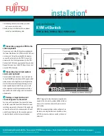
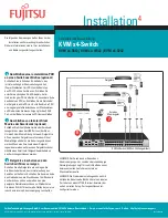
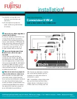
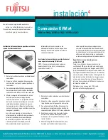
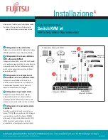
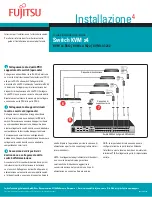
Page 1: ...he rear of your switch Connect the other end into the RJ 45 connector of the CAT 5 adapter cable 3 Connecting a target device to a CAT 5 adapter cable Connect a CAT 5 adapter cable into the appropriate port on the back of a target device Repeat steps 2 and 3 for all target devices you want to connect 4 Connecting network users Connect a customer supplied CAT 5 cable from the Ethernet network into ...

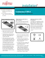
Page 2: ...t device must first be connected to the switch using a virtual media capable adapter cable To map a smart card with a target device the target device must first be connected to the switch using a smart card capable adapter cable 8 Turning on target devices and connecting power to the switch Turn on each target device then locate the power cords that came with the switch Connect one end into the po...

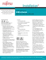
Page 3: ...to devices 2 Attach signal cables to connectors 3 Attach power cords to outlet 4 Turn device ON 5 To Disconnect Turn everything OFF 1 First remove power cords from outlet 2 Remove signal cables from connectors 3 Remove all cables from devices 4 Hazardous voltage current and energy levels are present inside any component that has the above label attached There are no serviceable parts inside these ...

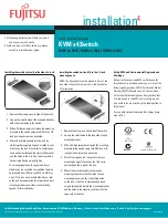
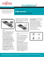
Page 4: ...cumentation for information about relocating side braces if they are not already spaced for this installation Installing the switch horizontally in the 1 U rack mounting space NOTE The filler panel must be placed in front of the rack when the switch is mounted in the horizontal 1 U orientation Remove the screws on each side of the switch 1 Line up the small holes in the long side of each 2 mountin...

Page 5: ...dere Ende am RJ 45 Anschluss des CAT 5 Adapterkabels an 3 Anschließen des Zielgeräts an ein CAT 5 Adapterkabel Schließen Sie das CAT 5 Adapterkabel an den entsprechenden Port an der Rückseite des Zielgeräts an Wiederholen Sie die Schritte 2 und 3 für alle Zielgeräte die angeschlossen werden sollen 4 Anschließen von Netzwerk Benutzern Schließen Sie eines der CAT 5 Kabel im Lieferumfang enthalten de...

Page 6: ...as Zielgerät zuerst mit einemVirtual Media fähigen Kabel an die Einheit angeschlossen werden Wenn eine Smartcard einem Zielgerät zugeordnet werden soll muss das Zielgerät zunächst mithilfe eines Smartcard fähigenAdapterkabels an den Switch angeschlossen werden 8 Zielgeräte einschalten und den Switch mit Strom versorgen Schalten Sie alle Zielgeräte ein und legen Sie die Stromkabel bereit das im Lie...

Page 7: ...nalkabel an die Anschlüsse 3 anschließen Die Stromkabel an Steckdosen anschließen 4 Gerät EINSCHALTEN 5 Abziehen Alle Geräte AUSSCHALTEN 1 Zuerst alle Stromkabel aus den Steckdosen 2 ziehen Die Signalkabel von den Anschlüssen 3 abziehen Alle Kabel von den Geräten abziehen 4 Gefährliche Spannung Strom und Energieniveaus befinden sich in allen Komponenten mit dem oben abgebildeten Aufkleber Im Inner...

Page 8: ...ion zum Rack nach wie die Seitenstreben versetzt werden können falls sie für diese Installation noch nicht auf den richtigen Abstand gebracht wurden Horizontale Switch Installation im 1 HE Rackplatz HINWEIS Die Blende muss vor dem Rack platziert werden wenn der Switch in der horizontalen 1 HE Position befestigt werden soll Entfernen Sie die Schrauben an jeder Seite des 1 Switches Richten Sie die k...

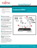
Page 9: ...l arrière du commutateur Branchez l autre extrémité au connecteur RJ 45 du câble adaptateur CAT 5 3 Connexion d un équipement cible à un câble adaptateur CAT 5 Connectez un câble adaptateur CAT 5 aux voies correspondantes à l arrière de l équipement cible Répétez les étapes 2 et 3 pour tous les équipements cibles à connecter 4 Connexion des utilisateurs du réseau Branchez un câble CAT 5 fourni par...

Page 10: ... compatibleVirtual Media Pour mapper une carte à puce à un équipement cible connectez d abord ce dernier au commutateur à l aide d un câble adaptateur compatible avec les cartes à puce 8 Mise sous tension des équipements cibles et alimentation du commutateur Mettez sous tension tous les équipements cibles puis munissez vous des cordons d alimentation fournis avec le commutateur Branchez une extrém...

Page 11: ...s 2 appareils Branchez les câbles d interface aux 3 connecteurs Branchez les cordons d alimentation sur les 4 prises Mettez l équipement sous tension 5 Débranchement Mettez tous les équipements hors tension 1 Débranchez d abord tous les cordons 2 d alimentation des prises Débranchez les câbles d interface des 3 connecteurs Déconnectez tous les câbles des équipements 4 Des niveaux de tension de cou...

Page 12: ...ez la documentation l accompagnant pour en savoir plus sur le déplacement des armatures latérales si leur écartement n est pas adapté à l installation Montage horizontal du commutateur dans un espace de montage 1 U NOTA Le panneau d obturation doit être placé à l avant du rack lorsque le commutateur est monté en position horizontale dans un espace 1 U Retirez les vis de chaque côté du commutateur ...

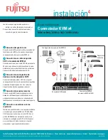
Page 13: ... Conecte el otro extremo en el conector RJ 45 del cable adaptador CAT 5 3 Conexión de un dispositivo de destino al cable adaptador CAT 5 Conecte el cable adaptador CAT 5 en el puerto correspondiente de la parte posterior del dispositivo de destino Repita los pasos 2 y 3 en todos los dispositivos de destino que desee conectar 4 Conexión de usuarios remotos Conecte un cable CAT 5 suministrado por el...

Page 14: ...edios virtuales Antes de asignar una tarjeta inteligente a un dispositivo de destino éste debe conectarse al conmutadormediante un cable adaptadorcompatible con tarjetas inteligentes 8 Encendido de los dispositivos de destino y conexión de la alimentación al conmutador Encienda cada uno de los dispositivos de destino y a continuación localice los cables de alimentación suministrados con el conmuta...

Page 15: ... los cables de alimentación a la 4 salida ENCIENDA el dispositivo 5 Para desconectar APÁGUELO todo 1 Primero extraiga los cables de la salida 2 Retire los cables de señal de los conectores 3 Retire todos los cables de los dispositivos 4 Existen niveles de voltaje corriente y energía peligrosos en todos los componentes que tengan la etiqueta anterior adherida a ellos Estos componentes no contienen ...

Page 16: ...car las abrazaderas laterales en caso de que no se disponga de suficiente espacio para llevar a cabo esta instalación Instalación del conmutador en posición horizontal en un espacio de montaje 1 U del rack NOTA El panel embellecedor debe colocarse delante del rack al montar el conmutador en posición horizontal 1 U Retire los tornillos colocados a ambos lados del 1 conmutador Alinee los orificios p...

Page 17: ...estremità al connettore RJ 45 del cavo adattatore CAT 5 3 Collegamento di un dispositivo di destinazione a un cavo adattatore CAT 5 Collegare un cavo adattatore CAT 5 alla porta corretta sul pannello posteriore di un dispositivo di destinazione Ripetere le fasi 2 e 3 per tutti i dispositivi di destinazione da collegare 4 Collegamento degli utenti di rete Collegare un cavo CAT 5 fornito dal cliente...

Page 18: ...funzionalità di supporto virtuale Per mappare una smart card su un dispositivo di destinazione il dispositivo di destinazione deve essere collegato allo switch tramite un cavo adattatore compatibile con smart card 8 Accensione dei dispositivi di destinazione e collegamento dello switch all alimentazione Accendere tutti i dispositivi di destinazione quindi individuare i cavi di alimentazione in dot...

Page 19: ... di alimentazione alle prese 4 di corrente Accendere il dispositivo 5 Per scollegare Spegnere tutte le apparecchiature 1 Scollegare i cavi di alimentazione dalle 2 prese di corrente Scollegare i cavi di segnale dai connettori 3 Scollegare tutti i cavi dai dispositivi 4 Questa etichetta indica la presenza di livelli di tensione e di corrente pericolosi all interno del componente Tali componenti non...

Page 20: ... contenute nella documentazione del rack Installazione orizzontale dello switch in uno spazio per montaggio su rack di formato 1U NOTA se l accessorio viene installato con orientamento orizzontale in uno spazio 1U il pannello di riempimento deve essere posizionato davanti al rack Rimuovere le viti da entrambi i lati dello switch 1 Allineare i fori piccoli sul lato lungo di ciascuna 2 staffa di mon...

Page 21: ... KVM s4スイッチへの接続 CAT 5ケーブル 4本ペア 最長45 m 150フィー ト の一方の端を スイッチの背面にある 番号が付いた利用可能なポートに接続しま す RJ 45コネクターの他の端をCAT 5アダプ ター ケーブルのRJ 45コネクターに接続し ます 3 ターゲット デバイスのCAT 5ア ダプター ケーブルへの接続 CAT 5アダプター ケーブルをターゲット デバイス後面の該当するポートに接続しま す 接続するすべてのターゲット デバイ スについて手順2と3を繰り返します 4 ネットワーク ユーザーの接続 ユーザー調達のイーサネット ネットワー クからのCAT 5ケーブルをスイッチ後面のLAN ポートに接続します ネットワーク ユー ザーはこのポートを介してスイッチにアク セスします 5 外付けモデムへの接続 オプ ション 本スイッチは ITU V 92 V 90 ...

Page 22: ...ン バーチャル メディア デバイスまたはス マート カード リーダーをスイッチのいず れかのUSBポートに接続します ターゲッ ト デバイスでバーチャル メディア セッ ションを開始するには ターゲット デバ イスがバーチャル メディア対応のアダプ ター ケーブルを使用して接続されている 必要があります ターゲット デバイスで スマート カードをマッピングするには まずターゲット デバイスをスマート カー ド対応のアダプター ケーブルを使用して スイッチに接続する必要があります 8 ターゲット デバイスの電源投 入とスイッチへの電源接続 各ターゲット デバイスの電源をオンに し 次にスイッチに付属の電源コードを取 り出します 一方の端をスイッチ後部にあ る電源ソケットに もう一方の端を適切な AC壁コンセントに接続します この手順を 二本目の電源コードで繰り返し システム 内の冗長電源装置...

Page 23: ...フにする 1 最初に コンセントから電源コードを 2 取り外す 信号ケーブルをコネクターから取り 3 外す すべてのケーブル類を装置から取り 4 外す 上記のラベルが付いているコンポーネント の内部には危険なレベルの電圧 電流 エ ネルギーが存在します これらのコンポー ネント内に修理可能な部品はありません それらの部品のいずれかに問題があると思 われる場合は サービス技術者に連絡してく ださい 機器をラックに収納する際の安全措置 ラックに収納するときは 以下の事項を考 慮してください 作動時の周辺温度の上昇 密閉された ラック アセンブリーや複数ユニットの ラック アセンブリーに機器を取り付け た場合 ラック環境での作動時の周辺温 度は 室内の周辺温度よりも高くなる可 能性があります 機器を作動温度に適応 した環境に取り付けてください 気流の減少 ラック内では 機器の安 全な作動に必要な...

Page 24: ... 向に設置する方法 注 スイッチを水平方向1Uに取り付ける場 合はフィラー パネルをラックの前に配置す る必要があります スイッチの各側面に付いているネジを 1 外します 各取付金具の 長い側 にある小穴と 2 スイッチのネジ穴を合わせます プラスのドライバーを使用し 8 32 3 x 1 2 インチのなべ頭ねじ2本を使用して 取 付金具を両側ともスイッチに締め付け ます 4個のケージ ナットまたはクリップ 4 ナットを ラックのラック取付フラン ジに取り付けます この時ナットは ラックの内側になるようにします 各取付金具の 短い側 の穴が 機器 5 のラックの合わせ穴に正しく合うよう にして スイッチ アセンブリをラック に収納します コンビネーション六角 頭ネジをブラケットの溝とマウント レールの穴を通して ケージナットま たはクリップナットまで差し込みます 安全性 EMC 環境に関す...

Reviews: