background image

System expansions

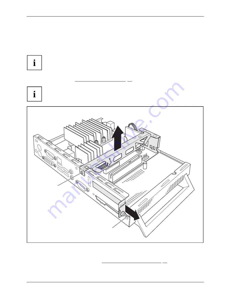
Retrofitting the DVI-D monitor port (optional)

If your device is not factory-

fi

tted with a DVI-D monitor port, you can retro

fi

t this as an option.

You can install either a PCI board or a DVI-D monitor port in the slot.

The DVI monitor port which is available for retro

fi

tting is a DVI-Digital (DVI-D) type

port. Therefore, only digitally accessible monitors can be connected.

Open the casing (see

"Opening the casing", Page 22

).

If a PCI board is installed, you must remove the cross piece and PCI board:

1

3

2

4

Undo the screws (1) and cables on the cross piece which are in the way.

Remove the cross piece (2).

Remove the PCI board, (see chapter

"Removing the PCI board", Page 27

).

If no PCI board is installed: Undo the screw of the slot cover (3) and remove the slot cover (4).

Fujitsu Technology Solutions

31

Summary of Contents for FUTRO S550-2

Page 1: ...Thin Client Operating Manual FUTRO S550 2 ...

Page 2: ...Desk list or look up the contact details on our website at http ts fujitsu com support servicedesk html your sales partner your sales office Further information can be found in the Safety and Warranty manuals The latest information about our products useful tips updates etc is available from our website http ts fujitsu com ...

Page 3: ......

Page 4: ...o modifications and delivery subject to availability Any liability that the data and illustrations are complete actual or correct is excluded Designations may be trademarks and or copyrights of the respective manufacturer the use of which by third parties for their own purposes may infringe the rights of such owner You will find more information at http ts fujitsu com terms_of_use html Order No Fu...

Page 5: ...FUTRO S550 2 Operating Manual Your FUTRO 5 Important notes 6 Getting started 9 Operation 18 System expansions 20 Technical data 34 Index 36 ...

Page 6: ... registered trademarks of their respective owners whose protected rights are acknowledged Copyright Fujitsu Technology Solutions GmbH 2009 All rights including rights of translation reproduction by printing copying or similar methods of the whole document or parts thereof are reserved Offenders will be liable to prosecution and payment of damages All rights reserved including rights created by pat...

Page 7: ...xternal devices to the parallel or serial port 15 Connecting external devices to the USB ports 16 Connecting microphone headphones line out and line in devices 16 Connecting the mains adapter 16 Connecting the device to the network LAN 17 Operation 18 Switch the device on 18 Switching off the device 18 Open BIOS Setup 18 PXE system boot 18 Calling the PXE system boot configuration menu 19 System e...

Page 8: ...Contents Technical data 34 Index 36 4 Fujitsu Technology Solutions ...

Page 9: ...cates an activity that must be performed Indicates a result This font indicates data entered using the keyboard in a program dialogue or at the command line e g your password Name123 or a command used to start a program start exe This font indicates information that is displayed on the screen by a program e g Installation is complete This font indicates terms and texts used in a software interface...

Page 10: ...emove the power plug from the power socket Replace the lithium battery on the mainboard in accordance with the instructions in Replacing the lithium battery Page 33 Caution components in the system can get very hot The activities described in these instructions must always be performed with the greatest care Repairs to the device must only be carried out by qualified technicians Incorrect repairs ...

Page 11: ...ipment switches and disconnect the power plug from the mains outlet Do not clean any interior parts yourself leave this job to a service technician Do not use any cleaning agents that contain abrasives or may corrode plastic alcohol thinner or acetone Never clean the device with water Water entering into the device could present a serious risk to users e g electric shock Ensure that no liquid ente...

Page 12: ...turning the equipment off and on the user is encouraged to try to correct the interference by one or more of the following measures Reorient or relocate the receiving antenna Increase the separation between equipment and the receiver Connect the equipment into an outlet on a circuit different from that to which the receiver is connected Consult the dealer or an experienced radio TV technician for ...

Page 13: ...s and operating elements on the device Please familiarise yourself with these components before starting to work with your device Front view Onswitch Offswitch Power onindicator SmartCardreader Flashmemoryaccess Headphoneport Audiooutput Microphoneport USB 5 4 3 2 6 7 1 1 SmartCard reader 2 Indicator for SmartCard reader 3 Flash memory access 4 Microphone jack 5 USB ports Universal Serial Bus 6 ON...

Page 14: ...ioinput PCIslot KensingtonLock 1 2 3 4 6 4 5 7 8 9 10 11 12 13 1 Cover 2 Serial port 3 Audio output Line out 4 USB ports Universal Serial Bus 5 DVI I monitor port 6 PS 2 keyboard port 7 DC input jack DC IN 8 Kensington Lock 9 PS 2 mouse port 10 Serial port 11 RJ45 socket Local Area Network 12 Audio input line in 13 PCI slot 10 Fujitsu Technology Solutions ...

Page 15: ...Vertical operating position Verticaloperatingposition Operatingposition vertical Basefeet Sidecover Use the supplied foot when the device is to be used in a vertical position Proceed as follows to operate the device in the vertical operating position Disconnect the cables if required Push the device onto the foot in the direction of the arrow If necessary reconnect any cables that were previously ...

Page 16: ...tion Operatingposition horizontal Basefeet Disconnect the cables if required Place the device on its upper side on a sturdy flat and clean surface Position the base feet on the underside of the device 1 1 1 1 Screw on the base feet with the screws 1 If necessary reconnect any cables that were previously disconnected 12 Fujitsu Technology Solutions ...

Page 17: ...ce and the external devices Please make sure that you always observe the safety notes provided in Important notes Page 6 Plug all data communication cables into the appropriate sockets Plug all power cables into the grounded mains outlets USB devices are hot pluggable This means you can connect and disconnect USB cables while your device is switched on Additional information can be found in Connec...

Page 18: ...ine Out light green Audiooutput Lineout USB Universal Serial Bus black UniversalSerialBus RJ45 LAN port LANport PS 2 mouse port green Mouseport PS 2mouseport PS 2 keyboard port purple Keyboardport Some of the connected devices require special software e g drivers refer to the documentation for the connected device and operating system Connecting the monitor Follow the instructions contained in the...

Page 19: ...rd cable into one of the device s USB ports USBport Connecting a PS 2 keyboard Use the supplied keyboard cable only ConnectingaPS 2keyboard Connecting Plug the rectangular connector of the keyboard cable into the rectangular socket on the underside or on the rear of the keyboard Plug the round plug of the keyboard cable into the keyboard port on the device Keyboard Connecting external devices to t...

Page 20: ...USB ports on your device Device drivers The external USB devices you connect to the USB ports usually require no driver of their own as the required software is already included in the operating system However if the external USB device requires its own software please install it from the data carrier provided with the USB device To ensure the transmission capacity of USB 2 0 the cable from the ex...

Page 21: ...Getting started Connecting the device to the network LAN LAN Connect the 10 100 1000 Base T network cable to the RJ45 LAN port Fujitsu Technology Solutions 17 ...

Page 22: ...ld lead to a loss of data If the device is in standby it consumes a minimum of energy Switch the device off at the main switch if present The device no longer uses any power The main switch and the ON OFF switch do not disconnect the device from the mains voltage To completely disconnect from the mains voltage remove the power plug from the power socket If necessary switch the monitor off see the ...

Page 23: ...The network is always started first before the local devices are activated PnP BEV BBS If a BBS BIOS BIOS Boot Specification exists the system is started by the BBS BIOS ROM Disabled The entire mechanism for the system boot is deactivated The system can only be activated via the local devices Int 18h The devices set in BIOS Setup are enabled Show Config Message The following message can be activat...

Page 24: ...ter beforehand The following illustrations may differ slightly from your device depending on its configuration level If further documentation was delivered with your device please also read this through carefully In addition before removing or installing system components please pay attention to the following The device must be switched off when installing removing the system expansions and may no...

Page 25: ...ou insert or remove boards Make sure expansion boards are inserted straightly Never use sharp objects screwdrivers for leverage Boards with electrostatic sensitive devices ESD are identifiable by the label shown When handling boards fitted with ESDs you must always observe the following points You must always discharge static build up e g by touching a grounded object before working The equipment ...

Page 26: ...ormation in Important notes Page 6 Disconnect the mains plug from the mains outlet Only insert the power plug after you have closed the casing Remove any connected wires which are in the way 3 2 2 1 1 Loosen the screws at the rear 1 Slide the casing cover in the direction of the arrow 2 Lift off the casing cover 3 22 Fujitsu Technology Solutions ...

Page 27: ... casing cover on the device and push it backwards Secure the casing cover with the two screws on the rear of the device Make sure that the cables are not trapped between the casing and the components Connect all the cables removed before Fujitsu Technology Solutions 23 ...

Page 28: ...e therefore recommend that you wait one hour after switching off the device before removing or installing the memory modules Otherwise there is a risk of suffering burns As some components are exposed that are sensitive to static electricity please take note of chapter Information about boards Page 21 Removing memory modules 3 2 1 1 Carefully push the two mounting clips outwards 1 Memoryexpansion ...

Page 29: ...ed settings for the PCI board Open the casing see Opening the casing Page 22 2 3 4 1 Undo the screw 1 and cables on the cross piece which are in the way Remove the cross piece 2 Insert the riser card in its slot 3 Refit the cross beam Undo the screw and remove the rear slot cover plate of the slot 4 Fujitsu Technology Solutions 25 ...

Page 30: ...ar slot cover plate due to cooling fire protection and the EMC regulations regulations on electromagnetic compatibility to be complied with 1 2 Insert your PCI board on the riser card 1 Secure the lock with the screw 2 to secure the PCI board Close the casing see Closing the casing Page 23 26 Fujitsu Technology Solutions ...

Page 31: ...ust reinstall the rear slot cover plate due to cooling fire protection and the EMC regulations regulations on electromagnetic compatibility to be complied with Now reinstall the rear slot cover plate by inserting it in the installation slot from the inside and securing it with the screw 1 Close the casing see Closing the casing Page 23 Fujitsu Technology Solutions 27 ...

Page 32: ... piece which are in the way Remove the cross piece 2 Remove the PCI board see chapter Removing the PCI board Page 27 Connect the cable to the SmartCard reader 3 and to the connector on the mainboard 4 With the component side facing downwards insert the SmartCard reader on the securing bolt in the direction of the arrow 5 Secure the SmartCard reader onto the carrier with the screws 6 Reinstall the ...

Page 33: ...System expansions Close the casing see Closing the casing Page 23 Make sure that the cables are not trapped between the casing and the components Fujitsu Technology Solutions 29 ...

Page 34: ...n the cross piece which are in the way Remove the cross piece 2 Remove the PCI board see chapter Removing the PCI board Page 27 Disconnect the cable from the SmartCard reader 3 and from the mainboard 4 Undo the screws 5 Lift the SmartCard reader from the securing bolt 6 Reinstall the cross piece and the PCI board see Installing the PCI board Page 25 Close the casing see Closing the casing Page 23 ...

Page 35: ...I Digital DVI D type port Therefore only digitally accessible monitors can be connected Open the casing see Opening the casing Page 22 If a PCI board is installed you must remove the cross piece and PCI board 1 3 2 4 Undo the screws 1 and cables on the cross piece which are in the way Remove the cross piece 2 Remove the PCI board see chapter Removing the PCI board Page 27 If no PCI board is instal...

Page 36: ...er cable to the mainboard 1 Place the DVI D monitor port in the slot 2 Ensure that you insert the lug 3 on the port correctly into the intended opening 4 Ensure that the locking lug 5 engages Refit the cross piece Close the casing 32 Fujitsu Technology Solutions ...

Page 37: ...mended by the manufacturer Do not dispose of lithium batteries with household waste They must be disposed of in accordance with local regulations concerning special waste Ensure that you observe the correct polarity when replacing the lithium battery Lithiumbattery Replacing Replacing Replacing lithiumbattery Battery The lithium battery holder exists in different designs that function in the same ...

Page 38: ...h height without base foot 250 mm 52 mm 191 mm Weight in basic configuration approx 1 6 kg including foot Ambient conditions Temperature Operation Transportation 15 C 35 C 25 C 60 C Clearance required to ensure adequate ventilation left right hand side rear top min 200 mm min 200 mm min 200 mm min 200 mm Condensation must be avoided during operation Mains adapter Electrical data Rated voltage 100 ...

Page 39: ...e following adapters with Limited Power Source may be used S26113 E519 V55 Model ADP 65HB AD S26113 E519 V15 Model 0335C2065 S26113 E557 V55 Model ADP 65JH AD S26113 E557 V65 Model PA 1650 65 Fujitsu Technology Solutions 35 ...

Page 40: ...ice drivers Serial port 12 Device opening 18 switching off 14 switching on 14 transporting 3 upgrades 16 Devices Connecting 11 Devices connecting 12 Disposal 3 Drivers Utilities DVD 3 E Energy saving 3 External devices Connecting 11 Ports 10 External devices connecting 12 F Flash memory access 5 G Getting started 5 H Headphone port 5 Headphones 10 connecting 12 Horizontal operating position 8 I Im...

Page 41: ...orts 5 10 Power on indicator 5 PS 2 keyboard port 6 PS 2 mouse port 6 10 PS 2 mouse connecting 11 port 11 PXE system boot 14 R Recycling 3 Removing memory see Adding memory 20 Replacing lithium battery 29 Replacing lithium battery 29 Retransportation 3 RJ45 LAN port 6 S Safety information 2 Serial port 6 10 11 Connecting devices 11 Serial port Settings 11 Servicing 16 Side cover 7 SmartCard reader...

Page 42: ...Index V Vertical operating position 7 38 Fujitsu Technology Solutions ...

Reviews: