Page 41 of 52
Onl
y
i
nt
e
nded
fo
r
a
ut
horis
e
d s
e
rv
ic
e
te
c
h
nic
ia
ns
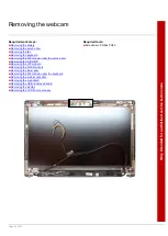
Removing the LCD panel
Required work steps:
■
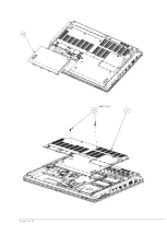
Removing the service door
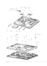
Removing the M.2 module of the keyboard
Removing the M.2 module under the service door
Removing the mains connection cable
Removing the USB / audio sub board
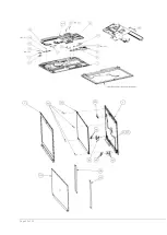
Removing the LCD front cover assy
Required tools:
■
Screwdriver: Phillips PH00
►
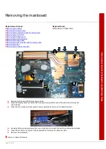
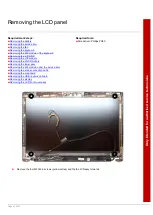
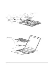
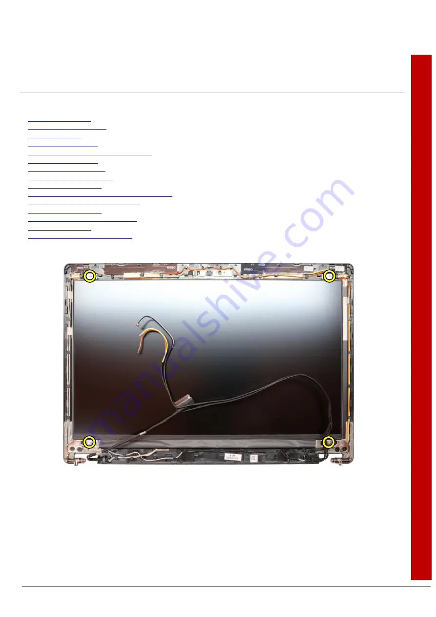
Remove the four M2XL2.5 screws (yellow circles) and flip the LCD assy forwards.
Summary of Contents for CELSIUS H7510
Page 47: ...Page 47 of 52 ...
Page 48: ...Page 48 of 52 ...
Page 49: ...Page 49 of 52 ...
Page 50: ...Page 50 of 52 ...
Page 52: ...Page 52 of 52 ...

