


En-11
PIPE INSTALLATION II
71
Sealing test
71 11
WARNING
Before operating the compressor, install the pipes and securely connect them.
•
Otherwise, if the pipes are not installed and if the valves are open when the
compressor operates, air could enter the refrigeration cycle. If this happens,
the pressure in the refrigeration cycle will become abnormally high and cause
damage or injury.
After the installation, make sure there is no refrigerant leakage. If the refrigerant
•
leaks into the room and becomes exposed to a source of fire such as a fan
heater, stove, or burner, it produces a toxic gas.
Do not subject the pipes to strong shocks during the sealing test. It can rupture
•
the pipes and cause serious injury.
CAUTION
For maintenance purposes, do not bury the piping of the outdoor unit.
•
After connecting the pipes, perform a sealing test.
•
Make sure that the 3-way valves are closed before performing a sealing test.
•
Pressurize nitrogen gas to 4.15 MPa to perform the sealing test.
•
Add nitrogen gas to both the liquid pipes and the gas pipes.
•
Check all flare connections and welds. Then, check that the pressure has not
•
decreased.
Compare the pressures after pressurizing and letting it stand for 24 hours, and
•
check that the pressure has not decreased. If the pressure has dropped, the pipe
joints may be leaking.
* When the outdoor air temperature changes 5 °C, the pressure changes 0.05 MPa
(0.5 bar). When outdoor air temperature raises/drops by 5 °C, the pressure will
raise/fall by 0.05 MPa accordingly.
If a leak is found, immediately repair it and perform the sealing test again.
•
After completing the sealing test, release the nitrogen gas from both valves.
•
Release the nitrogen gas slowly.
•
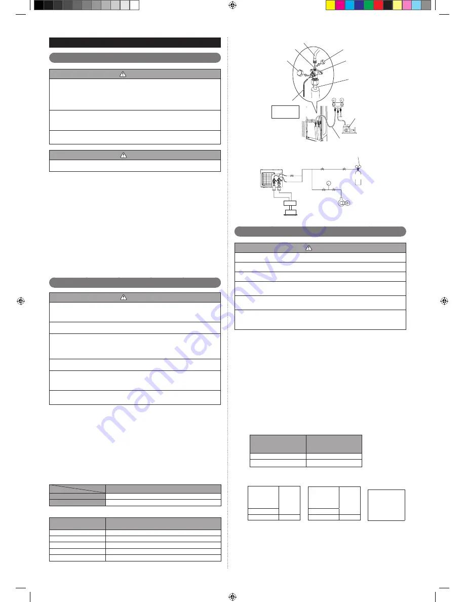
Vaccum process
71 21
CAUTION
Perform a refrigerant leakage test (air tightness test) to check for leaks using
•
nitrogen gas while all valves in the outdoor unit are closed. (Use the pressure
indicated on the nameplate.)
Be sure to evacuate the refrigerant system using a vacuum pump.
•
The refrigerant pressure may sometimes not rise when a closed valve is opened
•
after the system is evacuated using a vacuum pump. This is caused by the
closure of the refrigerant system of the outdoor unit by the electronic expansion
valve. This will not affect the operation of the unit.
If the system is not evacuated sufficiently, its performance will drop.
•
Use a clean gauge manifold and charging hose that were designed specifically
•
for use with R410A. Using the same vacuum equipment for different refrigerants
may damage the vacuum pump or the unit.
Do not purge the air with refrigerants, but use a vacuum pump to evacuate the
•
system.
Check that the valves are closed by removing the blank caps from the gas and
1
)
liquid pipes.
Remove the charging port cap, and connect the gauge manifold and the vacuum
2
)
pump to the charging valve with the service hoses.
Vacuum the indoor unit and the connecting pipes until the pressure gauge
3
)
indicates –0.1 MPa (-1bar).
When –0.1 MPa (-1bar) is reached, make sure it hold vacuum for 60 minutes.
4)
Disconnect the service hoses and fit the charging port cap to the charging valve
5
)
to the specified torque. (Refer to below table)
Remove the blank caps, and fully open the 3-way valves with a hexagon wrench
6
)
[Torque: 6 to 7 N·m (60 to 70 kgf·cm)].
Tighten the blank caps of the 3-way valve to the specified torque.
7
)
Tightening torque [N·m (kgf·cm)]
Charging port cap
10 to 12 (100 to 120)
3-way valve
6 to 7 (60 to 70)
Blank cap
[mm (in1)]
Tightening torque
[N·m (kgf·cm)]
6.35 (1/4)
20 to 25 (200 to 250)
9.52 (3/8)
20 to 25 (200 to 250)
12.70 (1/2)
25 to 30 (250 to 300)
15.88 (5/8)
30 to 35 (300 to 350)
19.05 (3/4)
35 to 40 (350 to 400)
Service hose
Service hose with valve core
Charging port
Blank cap
Hexagon wrench
Connecting pipe
Gauge manifold
Vacuum pump
Charging port cap
3-way valve
Use a 4 mm
(5/32") hexagon
wrench
Outdoor unit
Pressure regulating valve
Pressure gauge
Nitrogen
Vacuum pump
Branch box
Indoor unit
Additional charging
71 21
CAUTION
Do not turn on the power unless all operations are complete.
•
Do not charge the system with a refrigerant other than R410A.
•
Do not reuse recovered refrigerant.
•
Use an electronic scale to measure the charging amount of refrigerant.
•
Adding more refrigerant than the specified amount will cause a malfunction.
Charge refrigerant using the liquid pipe.
•
Adding refrigerant through the gas pipe will cause a malfunction.
Add refrigerant by charging the system with the refrigerant in the liquid state. If
•
the refrigerant cylinder is equipped with a siphon, it is not necessary to place the
cylinder upright.
Procedure for charging the system with refrigerant
71 21 11
Remove the charging cap from the liquid pipe.
1
)
Attach a charging hose to the refrigerant cylinder, and connect it to the charging
2
)
port.
Add refrigerant by calculating the additional refrigerant volume in accordance with
3
)
the calculation formula indicated below.
Remove the charging hose and install the charging cap.
4)
Remove the blank caps (gas pipe, liquid pipe), and open the valves.
5
)
Close the blank caps.
6
)
After adding refrigerant, indicate the added charging volume on the unit.
7
)
Tighten the blank caps and charging caps to the torque values specified.
*
To open and close the valves, use an M4 hexagon wrench for liquid and gas pipes.
Calculating the amount of refrigerant charge to be added
71 21 21
Round up the value to 2 decimal places.
•
Diameter of liquid
pipe
(mm (in.))
Additional amount for
pipe length
(kg/m)
Φ6.35 (1/4)
0.021
Φ9.52 (3/8)
0.058
Calculation of additional amount for pipe length
L =
Total length
of Φ6.35mm
(Φ1/4in.)
liquid pipe
× 0.021
kg/m
m
kg
+
Total length
of Φ9.52mm
(Φ3/8in.)
liquid pipe
× 0.058
kg/m
m
kg
=
Total
kg
<Example>
If liquid pipe piping length is the following
Φ9.52 (3/8) : 20m, Φ6.35 (1/4) : 15m
Additional charge volume L=20(m)×0.058(kg/m)+15(m)×0.021(kg/m)
=1.475kg
≒
1.48kg
9379069366_IM.indb 11
15/11/2555 11:18:23


