


En-2
2.3. Accessories
WARNING
For installation purposes, be sure to use the parts supplied by the manufacturer or other
prescribed parts.
The use of non-prescribed parts can cause serious accidents such as the unit to fall,
water leakage, electric shock, or fire.
The following installation parts are furnished. Use them as required.
Keep the installation manual in a safe place and do not discard any other accessories
until the installation work has been completed.
Do not discard any accessories needed for installation until the installation work has been
completed.
Name and shape
Q’ty
Application
Operating
manual
1
Installation
manual
1
(This book)
Operating
manual
(CD-ROM)
1
Template
1
For ceiling openings cutting,
also used as packing
Washer
8
For installing indoor unit
Coupler heat
insulation (large)
1
For indoor side pipe joint (large
pipe)
Coupler heat
insulation (small)
1
For indoor side pipe joint (small
pipe)
Cable tie (large)
4
For fixing the coupler heat
insulation.
Cable tie (me
-
dium)
2
For cable binding
Drain hose
1
For installing drain pipe VP25
(O.D.32, I.D.25)
Hose band
1
For installing drain hose
Drain hose
insulation B
1
Insulates the drain hose
2.4. Optional parts
Description
Model
Application
Cassette grille
UTG-UN*A-W
For AUXV004/007/009/012
UTG-UN*B-W
For AUXV014/018/024
External connect kit
UTY-XWZXZC
For output function
(Output terminal / CNB01)
UTY-XWZXZB
For control input function
(Apply voltage terminal / CNA01)
UTY-XWZXZD
For control input function
(Dry contact terminal / CNA02)
UTY-XWZXZ7
For forced thermostat off function
(Apply voltage terminal / CNA03)
UTY-XWZXZE
For forced thermostat off function
(Dry contact terminal / CNA04)
IR receiver unit
UTY-TRHX
For the wireless remote controller.
MODBUS® convertor
UTY-VMSX
For connecting to the Modbus network.
Wireless LAN adapter
UTY-TFSXZ*
For wireless LAN control.
External power supply
unit
UTZ-GXXA
Supply power to the indoor unit PCB when
the indoor unit is turned off to prevent errors.
3. INSTALLATION WORK
3.1. Selecting an installation location
Correct initial installation location is important because it is difficult to move unit after it is
installed.
WARNING
Select installation locations that can properly support the weight of the indoor. Install the
units securely so that they do not topple or fall.
CAUTION
Do not install the unit in the following areas:
• Area with high salt content, such as at the seaside.
It will deteriorate metal parts, causing the parts to fail or the unit to leak water.
• Area filled with mineral oil or containing a large amount of splashed oil or steam, such
as a kitchen.
It will deteriorate plastic parts, causing the parts to fail or the unit to leak water.
• Area that generates substances that adversely affect the equipment, such as sulfuric
gas, chlorine gas, acid, or alkali.
It will cause the copper pipes and brazed joints to corrode, which can cause refrigerant
leakage.
• Area that can cause combustible gas to leak, contains suspended carbon fibers or
flammable dust, or volatile flammables such as paint thinner or gasoline.
If gas leaks and settles around the unit, it can cause a fire.
• Area where animals may urinate on the unit or ammonia may be generated.
Do not use the unit for special purposes, such as storing food, raising animals, growing
plants, or preserving precision devices or art objects.
It can degrade the quality of the preserved or stored objects.
Do not install where there is the danger of combustible gas leakage.
Do not install the unit near a source of heat, steam, or flammable gas.
Install the unit where drainage does not cause any trouble.
Install the indoor unit, power supply cable, transmission cable, and remote controller
cable at least 1 m away from a television or radio receivers. The purpose of this is to
prevent TV reception interference or radio noise.
(Even if they are installed more than 1 m apart, you could still receive noise under some
signal conditions.)
If children under 10 years old may approach the unit, take preventive measures so that
they cannot reach the unit.
Decide the mounting position with the customer as follows:
(1) Install the indoor unit on a place having a sufficient strength so that it withstands
against the weight of the indoor unit.
(2) The inlet and outlet ports should not be obstructed; the air should be able to blow all
over the room.
(3) Leave the space required to service the air conditioner.
(4) A place from where the air can be distributed evenly throughout the room by the unit.
(5) Install the unit where connection to the outdoor unit (or RB unit) is easy.
(6) Install the unit where the connection pipe can be easily installed.
(7) Install the unit where the drain pipe can be easily installed.
(8) Install the unit where noise and vibrations are not amplified.
(9) Take servicing, etc., into consideration and leave the spaces. Also install the unit
where the filter can be removed.
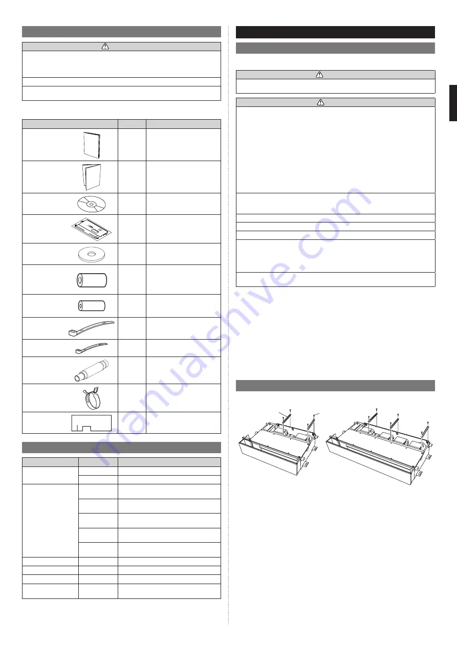
3.2. Preparation before installation
Remove the stays for transportation. Discard the stays and screws that you removed in
this step.
Stay
Screw
AUXV004/007/009/012
AUXV014/018/024
9384723017_IM.indb 2
14-Oct-20 13:29:46