


En-12
7. FIELD SETTING
There are 3 methods for address setting by FIELD SETTING as follows.
Set by either of the methods.
Each setting method is described (1) to (3) below.
(1) IU AD, REF AD SW settings: This section (7.1. Setting the address)
(2) Remote controller settings:
Refer to the wired or wireless remote controller manual
for detailed setting information. (Set IU AD, REF AD
SW to 0)
(3) Automatic address settings: Refer to the outdoor unit manual for detailed setting
information. (Set IU AD, REF AD SW to 0)
CAUTION
Be sure to turn OFF the power before performing the field setting.
Do not operate any switches other than prescribed, as it can cause the unit to operate
improperly or malfunction.
Use an insulated screwdriver to set the DIP switches.
7.1. Setting the address
Manual address setting method
The indoor unit address and the refrigerant circuit
address can also be set up through the wireless
remote controller.
IU AD
REF AD
RC AD
×10 ×1
×10 ×1
SET3
SET4
For refrigerant
circuit address
For indoor
unit address
CAUTION
Use an insulated screwdriver to set the DIP
switches.
Setting
Setting
range
Type of switch
Indoor unit address
• Rotary switch [IU AD × 1]
(Factory setting “0”)
• Rotary switch [IU AD × 10]
(Factory setting “0”)
When connecting multiple indoor units to 1
refrigerant system, set the address at IU AD SW
as shown in the Table A.
0 to 63
Setting example “2”
IU AD × 10
IU AD × 1
Refrigerant circuit address
• Rotary switch [REF AD × 1]
(Factory setting “0”)
• Rotary switch [REF AD × 10]
(Factory setting “0”)
In the case of multiple refrigerant systems, set
REF AD SW as shown in the Table A for each
refrigerant system.
Set to the same refrigerant circuit address as the
outdoor unit.
0 to 99
Setting example “63”
REF AD × 10 REF AD × 1
• If working in an environ-
ment where the wireless
remote controller can be
used, the addresses can
also be set using the
remote controller.
• If setting the addresses
using the wireless
remote controller, set
the indoor unit address
and refrigerant circuit
address to “00”.
(For information on set-
ting using the wireless
remote controller.)
* Do not set the indoor
unit address (IU AD
SW) at 64 to 99.
It may result in failure.
Table A
Address
Rotary switch
setting
Address
Rotary switch
setting
Refrigerant
circuit
REF AD SW
Indoor unit
IU AD SW
× 10
× 1
× 10
× 1
0
0
0
0
0
0
1
0
1
1
0
1
2
0
2
2
0
2
3
0
3
3
0
3
4
0
4
4
0
4
5
0
5
5
0
5
⁞
⁞
⁞
⁞
⁞
⁞
10
1
0
10
1
0
11
1
1
11
1
1
⁞
⁞
⁞
⁞
⁞
⁞
99
9
9
63
6
3
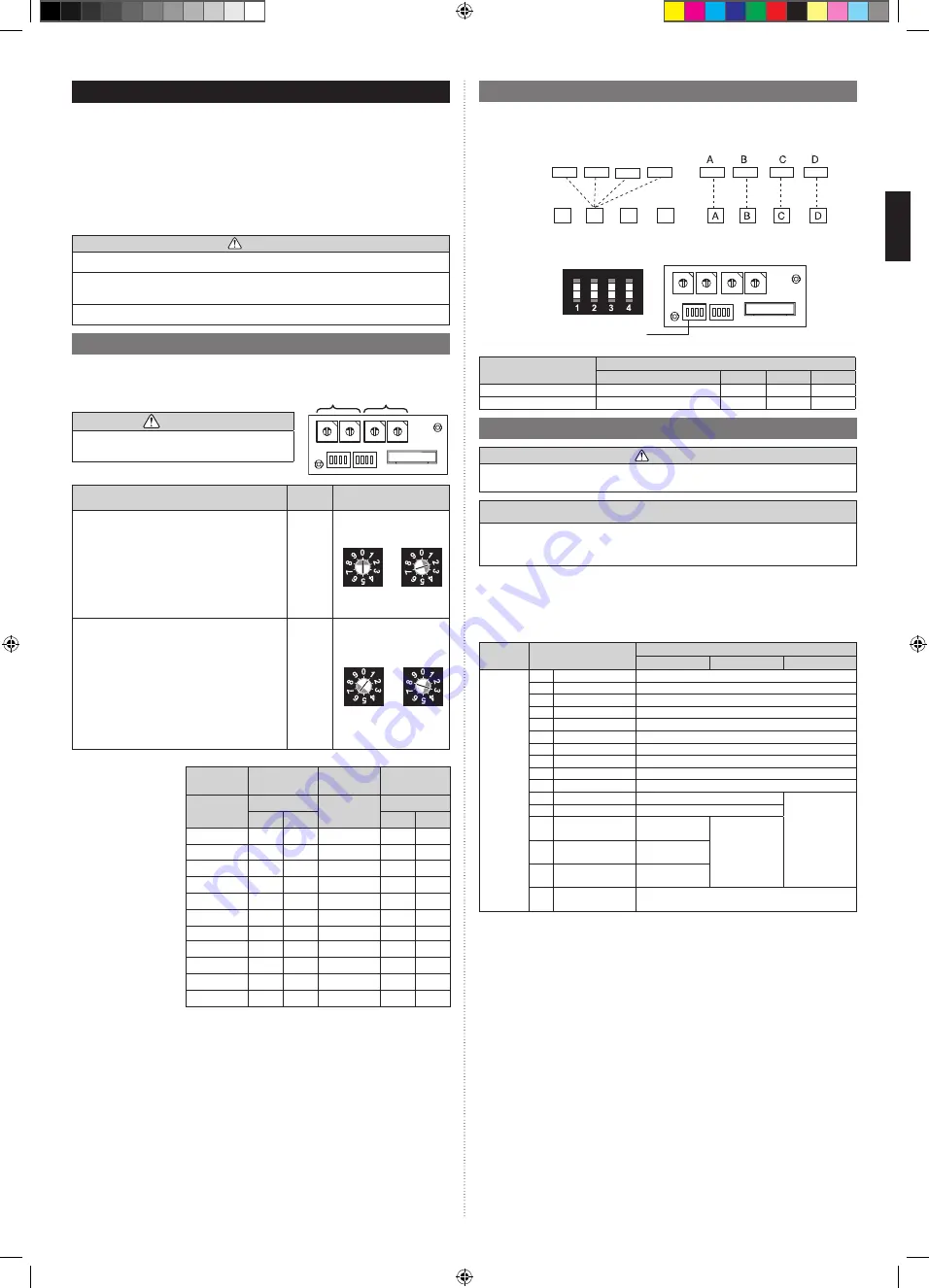
7.2. Custom code setting
Selecting the custom code prevents the indoor unit mix-up.
(Up to 4 codes can be set.)
Perform the setting for both the indoor unit and the remote controller.
Indoor
unit
Remote
controller
Confusion
Code change
Custom code setting for indoor unit
Set the DIP switch SET 3 SW1, SW2 referring to the Table B.
IU AD
REF AD
RC AD
×10 ×1
×10 ×1
SET3
SET4
SW 4
SW 3
SW 2
SW 1
Dip switch “SET 3”
ON
OFF
Table B
Custom code
A (Factory setting)
B
C
D
DIP switch SET3 SW1
OFF
ON
OFF
ON
DIP switch SET3 SW2
OFF
OFF
ON
ON
7.3. Static pressure mode
CAUTION
If the applicable static pressure does not match the static pressure mode, the static
pressure mode may be changed to another mode manually.
Recommended range of external static pressure
ARUM24: 0 and 0.56 in WG (0 and 140 Pa)
ARUM30: 0 and 0.44 in WG (0 and 110 Pa)
ARUM36: 0 and 0.36 in WG (0 and 90 Pa)
It is necessary to set up a static pressure mode for each usage of static pressure.
Static pressure can be set at site.
Relation between set values and static pressure are as the following table.
• FUNCTION SETTING can be performed with the wired or wireless remote controller.
(The remote controller is optional equipment)
• Refer to the wired or wireless remote controller manual for detailed setting information.
Function
Number
Setting Number
Setting Static Pressure
ARUM24
ARUM30
ARUM36
26
00
SP mode 00
0 in WG (0 Pa)
01
SP mode 01
0.04 in WG (10 Pa)
02
SP mode 02
0.08 in WG (20 Pa)
03
SP mode 03
0.12 in WG (30 Pa)
04
SP mode 04
0.16 in WG (40 Pa)
05
SP mode 05
0.20 in WG (50 Pa)
06
SP mode 06
0.24 in WG (60 Pa)
07
SP mode 07
0.28 in WG (70 Pa)
08
SP mode 08
0.32 in WG (80 Pa)
09
SP mode 09
0.36 in WG (90 Pa)
10
SP mode 10
0.40 in WG (100 Pa)
(0.36 in WG
(90 Pa))
11
SP mode 11
0.44 in WG (110 Pa)
12
SP mode 12
0.48 in WG
(120 Pa)
(0.44 in WG
(110 Pa))
13
SP mode 13
0.52 in WG
(130 Pa)
14
SP mode 14
0.56 in WG
(140 Pa)
31
Normal SP
(Factory setting)
0.16 in WG (40 Pa)
* Please refer to FAN PERFORMANCE CURVE within Design & Technical Data for the
features of each setting.
9373385264-02_IM_L3.indb Sec1:12
9373385264-02_IM_L3.indb Sec1:12
9/24/2019 11:06:30 AM
9/24/2019 11:06:30 AM


