background image

22 


Fixing of belt fixture 

An example of holding the Printer 


*Only in the case of the following example, the position of the hole for fixing the belt fixture is 

different from other cases.    Be careful. 


Fixing of belt fixture 

An example of holding the Printer 

Summary of Contents for 628WSL110H2

Page 1: ...Portable Thermal Printer FTP 628WSL User s Manual FUJITSU COMPONENT LIMITED ...

Page 2: ...on this Manual please do not hesitate to let us know This device complies with Part 15 of the FCC Rules Operation is subject to the following two conditions 1 This device may not cause harmful interference and 2 this device must accept any interference received including interference that may cause undesired operation The contents of this User s Manual may be subject to change without notice Pleas...

Page 3: ...ion of Respective Parts 13 5 Mounting of Paper Roll 23 6 Selecting Power Source of AC Adapter and Battery 26 7 Operating Switches 26 8 Status Indication Function by LED 27 9 Interface Connector Connection RS 232C Connecting Part 29 10 Interface Setting Dip Switch Operating Part 29 11 Function Specification 30 1 List of Commands 30 2 Test Printing 32 12 Hardware Specification 33 13 Recording Paper ...

Page 4: ...or atomic power control For uses in such applications please contact the sales representatives of our Company beforehand Indication of Warning Label With the view to protecting the users and other persons from the risk of injuries and avoiding damage of properties the matters that should be strictly observed are indicated in the following manner Danger indicates an imminent risk of causing severe ...

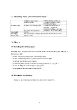
Page 5: ... the contact of the blade Precautions The Company shall not be held responsible for any trouble caused as a consequence of using separately sold items or consumables other than those designated in this Manual Never attempt to disassemble or repair any portion other than those indicated in this Manual The Company shall not be held responsible for any injury caused as a consequence of improper handl...

Page 6: ...ure during printing do not touch them directly Since heat is not radiated immediately after the printer is stopped touching it at this stage may cause a burn Fire Do not use a voltage other than the specified voltage of power supply to avoid the risk of fire or electric shock Do not put a metal or flammable substance in the inside of the aperture for insertion or ejection of paper to avoid fire or...

Page 7: ...o not use at places exposed to excessive humidity oily smoke or dust or in the environment with corrosive gases It may cause a fire or electric shock If you notice power failure or other abnormalities during the use stop the use immediately In the case of AC adapter unplug the power cord A fire or electric shock may be caused Do not fail to contact our sales representatives Do not cover or wrap AC...

Page 8: ...causing leaked liquid Soldering and heating up battery pack and battery Do not solder a battery pack terminal Soldering may cause melted case by generated heat or destruction of internal circuits leading to inoperable safety system that generates heat fire or destruction Heating the battery up to 100 C or higher may damage resin parts such as gaskets or the separator leading to leaked liquid or in...

Page 9: ...y made for this Printer 10 When exchanging the roll paper be careful not to be clipped your hand at opening and closing of paper cover or not to touch the paper cutter 11 Do not peep into through IrDA communication window especially while communication is being made 12 When not using for long period When you do not expect to use for a long period of time keep the recording paper inserted If the pr...

Page 10: ... model note Battery FUJITSU COMPONENT LIMITED NA02001 L032 AC adapter1 KAMI ELECTRONICS INDUSTRY Co Ltd KSW523U AC adapter2 Nagano Japan Radio Co Ltd SQS15W5P 10 AC adapter2 code setA Longwell LP 21 CEE 7 XVII AC adapter2 code setB KAWASAKI ELECTRIC WIRE CO LTD KP 610 BS1363 ...

Page 11: ...tion This manual is an explanation of the content of the above mentioned main body As for the following accessories such as AC adaptors and the belt fixture an accesso ry composition is different because of the order printer type AC adaptors belt fixture battery roll paper The set or use is described in this user s manual ...

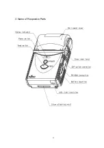
Page 12: ...11 3 Name of Respective Parts ...

Page 13: ...12 ...

Page 14: ... on when power is switched on Further when some errors happen the lamp indicates its status The status indication lamp might not be seen easily in a bright place under direct sunshine etc Power switch This is the switch to turn on off the power Please do not operate two seconds after cutting the power supply About two seconds after cutting the power supply the operation becomes invalid Feed switch...

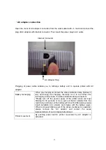
Page 15: ...and during the charging the lamp is on in red When the recharging is fully made the status indication lamp will extinct Please turn off the power supply of the printer when red kept blinking for 30 seconds or more pull out the AC adaptor from the main body and take out the battery p16 to p18 Afterwards please insert installation AC adaptor and charge with the battery again When red keeps blinking ...

Page 16: ...de marked with and manipulate the dip switch inside This is used when printer setting is changed Dip Switch RS 232C connecting part Open the cover of RS 232C connecting part from the side marked with and connect RS 232C cable separately available to internal connector RS 232C Connector ...

Page 17: ...ng they will not open Operate in accordance with the following steps Mounting 1 Turn the Printer upside down and put it on the table 2 Remove the battery lid As shown in the enlarged illustration pull up the lid while pressing the hook of the battery lid to the direction of the arrow Enlarged illustration of the circulated part ...

Page 18: ...ift it with too much vigor the battery locking plate may break Handle carefully 4 Mount the battery Make sure that the sides of the battery is in the same direction as the indication on the battery locking plate The battery label might be different from the one in the photograph ...

Page 19: ...tery push the battery locking plate at the side indicated with mark 6 Fix the battery lid While pushing the lid to the direction indicated by arrow push the hook of battery lid to the direction indicated by arrow to close the lid ...

Page 20: ...19 Exchange of battery 1 Follow the same steps 1 to 3 for mounting 2 Tilt the printer and take out the battery pack 3 Follow the same steps 4 to 6 for mounting ...

Page 21: ...ing data by way of IrDA communications Do not peep into through IrDA communication window Especially pay special attention when communication is being carried out For data transmission use under the following conditions Transmission distance 300 mm angle 15 600 mm angle 8 ...

Page 22: ...ture with the screws attached to the Printer Portions indicated with circles function as stoppers for belt fixture Belt fixture may be mounted in the following three manners Belt fixture should not touch or run on battery locking plate or stopper Fixing of belt fixture An example of holding the Printer ...

Page 23: ... An example of holding the Printer Only in the case of the following example the position of the hole for fixing the belt fixture is different from other cases Be careful Fixing of belt fixture An example of holding the Printer ...

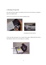
Page 24: ...d for mounting the paper roll is explained below 1 Move the cover open lever to the direction indicated by arrow Enlargement of encircled portion 2 This is the state when paper cover is opened At the portion indicated with arrow lies the cutter blade Be careful not to cut your finger etc accidentally ...

Page 25: ... the paper roll into the paper holder In the case of new roll the end of the paper may still hold adhesive Draw the paper a little longer and set it 4 Press the center part of the paper cover and close it firmly ...

Page 26: ...25 5 Cut the paper by moving it to the direction indicated by arrow ...

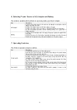
Page 27: ...cuts the power supply 7 Operating Switches This Printer is operated using two switches Item Description Power switch 1 Press this switch to turn on the printer power 2 When the power is turned on LED blinks according to the printer status and printer becomes ready for operation 3 When turning off the printer power if the process including registration to the flash memory in progress turn off the p...

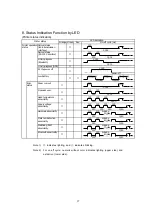
Page 28: ...0 125 125 5 times 250 125 125 6 times 250 125 125 7 times 250 125 125 8 times 250 Error status Head temperature abnormality Watchdog RAM abnormality Bluetooth abnormality 1 000 Paper run out Opened cover At the power off Printer status Printer operation status 1 000 Link in progress Bluetooth Low battery Normal status radio transmission interface 1 000 Normal status RS 232C interface Supply voltag...

Page 29: ...orange Bluetooth F W Download in progress Battery charge status indication This indicates the battery charge status Note 1 indicates lighting and indicates blinking Note 2 For on off cycle upper side indicates lighting and lower side indicates extinction Maintenance status indication This indicates the printer maintenance status Note 1 indicates lighting and indicates blinking ...

Page 30: ... 12 N C Not connected Note Input and output are defined from the printer side For pin number refer to the figure below 3 Connector model No RL01 P12S C Japan Aviation Electronics Industry Ltd or equivalent 10 Interface Setting Dip Switch Operating Part Bit No Function Setting Description OFF Wireless interface 1 Interface setting ON Wired interface OFF Teletype protocol mode 2 Communication mode O...

Page 31: ... ESC D n Horizontal tab position setting 17 ESC J n Printing and minimum pitch unit paper feed 18 ESC K n Backward paper feed 19 ESC L Page print mode selection 20 ESC R n International character specification 21 ESC S Print area setting in page print mode 22 ESC V n Right rotation 90 23 ESC W X1 X2 Y1 Y2 dX1 dX2 dY1 dY2 Print area setting in page mode 24 ESC X m n Sleep mode time setting 25 ESC c...

Page 32: ... 41 GS E n Print quality setting 42 GS a n Setting and cancellation of status transmission 43 GS e n m Bar code width setting 44 GS h n Bar code height setting 45 GS k m n d1 to dn Bar code printing 46 GS A ENQ Bluetooth information printing 47 ESC Y SOH x a DLE n RS 232C communication condition setting RS RS 232C BT Bluetooth IR IrDA valid for with without sequence mode valid for without sequence...

Page 33: ...unction 2 To make test printing press power switch while pressing feed switch of operating switch The status indication lamp will put on green and the test printing is started The printer will stop printing after printing a certain set length Example of test printing ...

Page 34: ...age mode Max No of dots line 384 IrDA Communication method IrDA Ver 1 2 Baud rate 9 600 bps 19 200 bps 38 400 bps 115 2 kbps Communication mode Semi duplex Protocol stack IrLAP IrLMP IrIAS TinyTP IrCOMM RS 232C Communication mode Semi Full duplex Baud rate 9 600 bps Max 115 2 kbps Interface Bluetooth Communication method Bluetooth Ver 2 0 EDR Modulation method FHSS GFSK Transmission speed 460 kbps...

Page 35: ... or less 14 Others 1 Handling of recording paper Recording paper will get colored due to chemical reaction When handling it pay attention to the following points Do not store it at high temperature high humidity place Do not store for a long time at a place exposed to direct sun light Do not use solvent type glue for pasting Do not let it get in touch with plastic film containing plasticiser for a...

Page 36: ...l use IPA Isopropyl alcohol available in the market Portion indicated by a box is thermal head 3 Wipe off with dry soft cloth and wait until it dries naturally Shut the paper cover Cleaning of roller Once a month 1 Open the roll paper cover Refer to Page 22 5 Paper setting 1 2 Wipe off the stain with alcohol pasted cloth For alcohol use IPA Isopropyl alcohol available in the market Portion indicat...

Page 37: ...ion indicated by a box is photo sensor Cleaning of IrDA receiving and transmitting part When the stains are visible Portion indicated by a box is IrDA receiving and transmitting part 1 Moist the cloth with neutral detergent Lightly wipe off the stains 2 Dip the cloth into water and wring it Wipe off well the detergent with this cloth 3 Wipe with dry soft cloth ...

Page 38: ...on 1 Keep the printer with paper cover opened Press the opening closing supporting points of the paper cover to the frame and fix the cover The encircled parts are supporting points 2 Open and close the paper cover once or twice and make sure that the opening closing can be carried out smoothly ...

Page 39: ...municating under the direct sunlight Press the power switch on Check the recording paper setting Refer to page 23 Recharge the battery Release the error mode Refer to page 27 Close the paper holder cover properly Either reduce the distance or adjust the angle Clean the window Refer to page 36 Check the dip switch setting Refer to page 29 Avoid direct sunlight Printing too dim Isn t the thermal hea...

Page 40: ...evision reception which can be determined by turning the equipment off and on The user is encouraged to try to correct the interference by one of the following measures Reorient or relocate the receiving antenna Increase the separation between the equipment and receiver Connect the equipment into an outlet on a circuit different from that to which the receiver is connected Consult the dealer or an...

Reviews: