background image

En-7

5. PIPE INSTALLATION-1

5.1. Opening a knock out hole


CAUTION

Be careful not to deform or scratch the panel while opening the knock out holes.
To protect the piping insulation after opening a knock out hole, remove any burrs from 

the edge of the hole. It is recommended to apply rust prevention paint to the edge of the 

hole.

• 

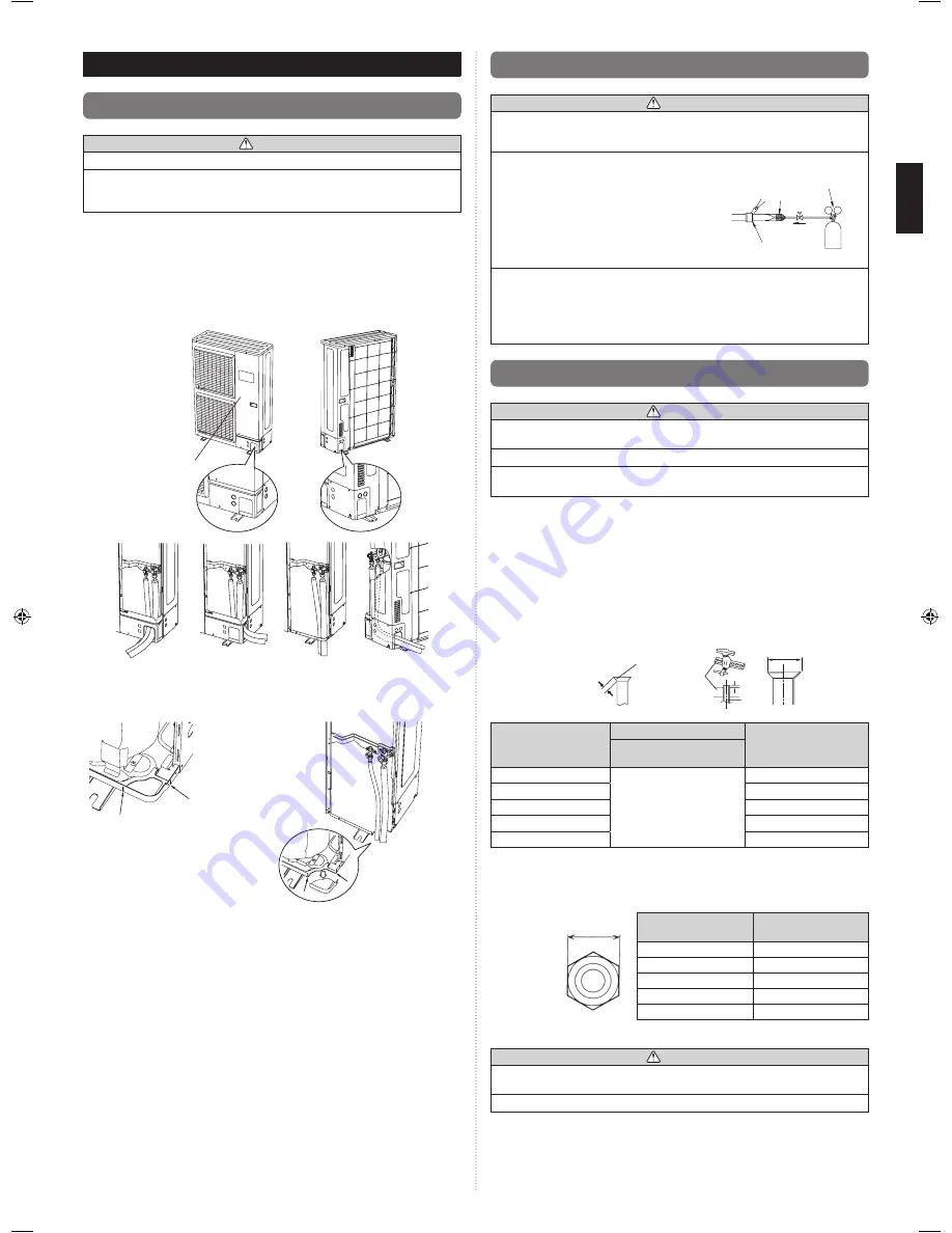
Pipes can be connected from 4 directions, front, lateral side, rear side and bottom.  

(Fig. A)

• 

When connecting at the bottom, remove the service panel and piping cover on the 

front of the outdoor unit, and open the knock out hole provided at the bottom corner of 

the piping outlet.

• 

It can be installed as shown on “Fig. B” cutting out the 2 slits as indicated on “Fig. C”. 

(When cutting slits, use a steel saw.)

  Fig. A

Service panel

Front  

connection

Bottom  

connection 

(No. 1)

Lateral

connection

Rear  

connection


Fig. B 

             Fig. C

Slit

Slit


Bottom  

connection

(No. 2)

5.2. Brazing

 CAUTION

If air or another type of refrigerant enters the refrigeration cycle, the internal pressure in 

the refrigeration cycle will become abnormally high and prevent the unit from exerting its 

full performance. 
Apply nitrogen gas while brazing the pipes. If a pipe is brazed without applying nitrogen 

gas, an oxidation film will be created.


This can degrade performance or damage the  

parts in the unit (such as the compressor or  

valves).

Pressure regulating valve

Cap

Brazing area

Nitrogen gas

Nitrogen gas pressure: 0.02 MPa  

(= pressure felt sufficiently on 


the back of the hand)

For brazing material, use phosphor copper that does not require flux. Do not use flux to 

braze pipes. If the flux is the chlorine type, it will cause the pipes to corrode.


Furthermore, if the flux contains fluoride, it will adversely affect the refrigerant pipe 

system such as by degrading the refrigerant. 

If fluoride is contained, quality of refrigerant deteriorates and affects the refrigerant 

piping system.

5.3. Flare connection (pipe connection)

 CAUTION

Do not use mineral oil on a flared part. Prevent mineral oil from getting into the system 

as this would reduce the lifetime of the units.
While brazing the pipes, be sure to blow dry nitrogen gas through them.

The maximum lengths of this product are shown in the table. If the units are further apart 

than this, correct operation cannot be guaranteed.

5.3.1. Flaring

Use special pipe cutter and flare tool exclusive for R410A.

(1)  Cut the connection pipe to the necessary length with a pipe cutter.
(2)  Hold the pipe downward so that the cuttings will not enter the pipe and remove any 

burrs.

(3)   Insert the flare nut (always use the flare nut attached to the indoor and outdoor 

units respectively) onto the pipe and perform the flare processing with a flare tool.


Leakage of refrigerant may result if other flare nuts are used.

(4)  Protect the pipes by pinching them or with tape to prevent dust, dirt, or water from 

entering the pipes.

Check if [L] is flared uniformly

and is not cracked or scratched.

B

L

Pipe

A

Die

Pipe outside diameter 

[in. (mm)]

Dimension A [in. (mm)]

Dimension B [in. (mm)]

Flare tool for R410A, 

clutch type

1/4 (6.35)

0 to 0.020

(0 to 0.5)

3/8 (9.1)

3/8 (9.52)

1/2 (13.2)

1/2 (12.70)

5/8 (16.6)

5/8 (15.88)

3/4 (19.7)

3/4 (19.05)

15/16 (24.0)

When using conventional  flare tools to flare R410A pipes, the dimension A should  be 

approximately 0.020 in. (0.5 mm) more than indicated in the table (for flaring with R410A 

flare  tools)  to  achieve  the  specified  flaring.  Use  a  thickness  gauge  to  measure  the 

dimension A.

Width across 

flats

Width across

flats

Pipe outside 

diameter [in. (mm)]

Width across flats of 

Flare nut [in. (mm)]

1/4 (6.35)

11/16 (17)

3/8 (9.52)

7/8 (22)

1/2 (12.70)

1 (26)

5/8 (15.88)

1-1/8 (29)

3/4 (19.05)

1-7/16 (36)

5.3.2. Bending pipes

 CAUTION

To prevent breaking of the pipe, avoid sharp bends. Bend the pipe with a radius of 

curvature of 3-15/16in. (100mm) to 5-14/16in. (150mm).
If the pipe is bent repeatedly at the same place, it will break.

• 

If pipes are shaped by hand, be careful not to collapse them.

• 

Do not bend the pipes at an angle of more than 90°.

•  When pipes are repeatedly bent or stretched, the material will harden, making it difficult 

to bend or stretch them any more.

• 

Do not bend or stretch the pipes more than three times. 

9379069762_IM.indb   7

3/4/2016   09:03:13

Summary of Contents for 30RLXEH

Page 1: ...IT Français Español APPAREIL EXTÉRIEUR UNIDAD EXTERIOR INSTALLATION MANUAL For authorized service personnel only MANUEL D INSTALLATION MANUAL DE INSTALACIÓN Pour le personnel d entretien autorisé uniquement Únicamente para personal de servicio autorizado ...

Page 2: ...ofessional or improper installation of the product may cause serious accidents such as injury water leakage electric shock or fire If the outdoor unit is installed in disregard of the instructions in the installation manual it will void the manufacturer s warranty Do not turn on the power until all work has been completed Turning on the power before the work is completed can cause serious accident...

Page 3: ...ual To connect the indoor unit and outdoor unit use air conditioner piping and cables available locally as standard parts This manual describes proper connections using such installation set Do not use an extension cable Do not purge the air with refrigerants but use a vacuum pump to vacuum the installation There is no extra refrigerant in the outdoor unit for air purging Using the same vacuum pum...

Page 4: ...th R410A are as shown in the table Never use copper pipes thinner than those indicated in the table even if they are available on the market Thicknesses of Annealed Copper Pipes R410A Pipe outside diameter in mm Thickness in mm 1 4 6 35 0 032 0 80 3 8 9 52 0 032 0 80 1 2 12 70 0 032 0 80 5 8 15 88 0 039 1 00 3 4 19 05 0 047 1 20 3 3 Protection of pipes Protect the pipes to prevent the entry of moi...

Page 5: ...eaker If children under 10 years old may approach the unit take preventive measures so that they cannot reach the unit Keep the length of the piping of the indoor and outdoor units within the allowable range For maintenance purposes do not bury the piping 4 2 Drain installation CAUTION In places where the outdoor temperature drops to 32 F 0 C or lower the drain water may freeze and may stop up the...

Page 6: ... the bottom hands or fingers may be pinched Carry slowly in the manner as shown on Fig B holding the handles Fig A in right and left sides Be careful not to touch with hands or objects Be sure to hold the handles on the sides of the unit Otherwise the suction grilles on the sides of the unit may be deformed Fig A Handle Suction grille Handle Suction grille Fig B Front view Rear view 4 5 Installati...

Page 7: ... Prevent mineral oil from getting into the system as this would reduce the lifetime of the units While brazing the pipes be sure to blow dry nitrogen gas through them The maximum lengths of this product are shown in the table If the units are further apart than this correct operation cannot be guaranteed 5 3 1 Flaring Use special pipe cutter and flare tool exclusive for R410A 1 Cut the connection ...

Page 8: ...nd cause damage or injury After the installation make sure there is no refrigerant leakage If the refrigerant leaks into the room and becomes exposed to a source of fire such as a fan heater stove or burner it produces a toxic gas Do not subject the pipes to strong shocks during the sealing test It can rupture the pipes and cause serious injury CAUTION Do not block the walls and the ceiling until ...

Page 9: ...does not include the concurrent use of other devices Do not start operation until the refrigerant is charged completely The compressor will fail if it is operated before the refrigerant piping charging is complete Transmission cable between indoor unit and outdoor unit is 240 V Be sure not to remove thermistor sensor etc from power wiring and connection wiring Compressor may fail if operated while...

Page 10: ... a protection sleeve for the conduits can be inserted at the knock out hole If you do not use a wire conduit be sure to protect the wires to prevent the edge of the knock out hole from cutting the wires It is recommended to apply anti rust paint to the edge of the knock out hole Knock out holes are provided for wiring Fig A Knock out holes are provided 2 each in the same size in front lateral and ...

Page 11: ...tion for using an insulation material with equal heat transmission rate or below 0 040 W m k Relative humidity in mm Insulation material Minimum thickness in mm 70 or more 75 or more 80 or more 85 or more Pipe diameter 1 4 6 35 5 16 8 13 32 10 16 32 13 21 32 17 3 8 9 52 11 32 9 7 16 11 18 32 14 23 32 18 1 2 12 70 13 32 10 15 32 12 19 32 15 3 4 19 5 8 15 88 13 32 10 15 32 12 5 8 16 25 32 20 If the ...

Page 12: ...uring abnormal air conditioner operation 3 PUMP DOWN L1 Orange Lights on during pump down operation 4 LOW NOISE MODE L2 L3 Orange Lights on during Low noise function when field setting is activated Lighting pattern of L2 and L3 indicates low noise level See page 13 5 PEAK CUT L4 L5 L6 Orange Lights on during Peak cut function when local setting is activated Lighting pattern of L4 L5 and L6 indicat...

Page 13: ...e PEAK CUT L4 L5 L6 Level 1 Blink Level 2 Blink Sign Lights off The noise of Level 2 is lower than the one of Level 1 6 Press ENTER button SW3 and fix it PEAK CUT L4 L5 L6 Level 1 Level 2 Sign Lights off Lights on 7 Return to Operating status display Normal operation by pressing EXIT button SW4 In case of missing how many times SELECT and ENTER button are pressed restart from the beginning of oper...

Page 14: ...ction 10 1 External input 10 1 1 Wiring of connector ON OFF of the Low noise mode and Peak cut mode functions can be enabled with an external field device When installing connection cable specified part optional parts must be used Refer to section 9 2 Table Settings List for the required function The function must be set for the external input to work Input Connector No Optional parts Low noise mo...

Page 15: ...ete the outdoor units and the connected indoor units will start operating Room temperature control will not activate during test operation continuous operation If a knocking sound can be heard in the liquid compression of the compressor stop the unit immediately and then energize the crank case heater for a sufficient length of time before restarting the operation 11 2 1 Setting method on outdoor ...

Page 16: ...r Heat sink temp sensor error 2 8 4 Current sensor error Current sensor 1 error stoppage permanently 2 8 6 Pressure sensor error High pressure switch 1 error 2 8 6 Pressure sensor error 2 9 4 Trip detection Trip detection 2 9 5 Compressor motor control error Rotor position detection error stoppage permanently 2 9 7 Outdoor unit fan motor 1 error Duty error 2 9 8 Outdoor unit fan motor 2 error Duty...

Page 17: ...D display lights on as shown in the above figure and the fans and the compressor start operating If the PUMP DOWN button is pressed while the compressor is operating the compressor will stop then start again in about 3 minutes 4 LED display will change as shown below about 3 minutes after the compressor starts Fully close the 3 way valve on the liquid pipe side at this stage POWER MODE ERROR PUMP ...

Reviews: