background image


System expansions


A26361-K680-Z122-1-7619, Edition 1 

59 


Installing second processor 

The mainboard can be upgraded by a second processor if it is inserted into the slot for the second 

processor. 


Remove the ventilation duct (see the section "Removing ventilation duct"). 


1


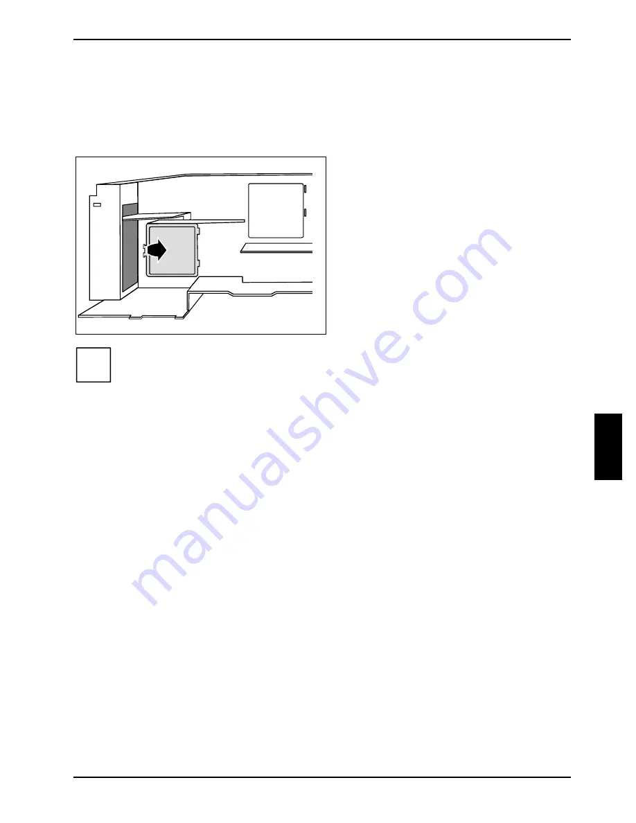
Open the tab (1) on the underside of the 
ventilation duct. 


Remove the blind cover of the ventilation 
duct in the direction of the arrow. 


i


Do not throw away the blind cover. For cooling and protection against fire you must refit 
the cover if you remove the processor again later. 


Install the second processor as described in the technical manual for the mainboard. 


Refit the ventilation duct (see section "Installing ventilation duct"). 


Close the casing (see "Closing the casing" chapter). 

Summary of Contents for CELSIUS R630

Page 1: ...Operating manual CELSIUS R630 V810 English answers2 ...

Page 2: ...ike to be clarified Please contact your sales partner your sales outlet Further information can be found in the Safety Ergonomics and Warranty manuals The latest information on our products tips updates etc can be found on the internet under http www fujitsu siemens com ...

Page 3: ......

Page 4: ...Herausgegeben von Published by Fujitsu Siemens Computers GmbH Printed in the Federal Republic of Germany AG 0704 07 04 Ausgabe Edition 1 Bestell Nr Order No A26361 K680 Z122 1 7619 ...

Page 5: ...CELSIUS R630 V810 Operating manual Introduction Important notes Preparing for use Operation Troubleshooting and tips System expansions Technical data Index July 2004 edition ...

Page 6: ...poration All other trademarks referenced are trademarks or registered trademarks of their respective owners whose protected rights are acknowledged Copyright Fujitsu Siemens Computers GmbH 2004 All rights including rights of translation reproduction by printing copying or similar methods in part or in whole are reserved Offenders will be liable for damages All rights including rights created by pa...

Page 7: ...ternal devices 11 Connections on the workstation 12 Connecting external devices to the serial port 13 Connecting external devices to the parallel port 13 Connecting external devices to the USB ports 14 Operation 15 Switching the workstation on 15 Switching off the workstation 15 Indicators on the workstation 16 Keyboard 18 Important keys and key combinations 19 Working with floppy disks 20 Setting...

Page 8: ...nt panel 37 Attaching the front panel 38 Installing an accessible drive 39 Removing an accessible drive 41 Changing the floppy disk drive 43 Installing or removing the hard disk drive 45 Installing and removing SmartCard reader 48 Installing and removing front USB or USB audio ports 51 Extensions to the mainboard 55 Removing ventilation duct 55 Installing ventilation duct 56 Upgrading main memory ...

Page 9: ...p also allow you to protect your data by means of passwords In addition you can also mechanically lock your workstation Systems with a SmartCard reader offer additional protection DeskUpdate allows you under some operating systems to easily and quickly install the latest drivers and operating system extensions with a few mouse clicks DeskUpdate is contained on the Drivers Utilities CD Additional i...

Page 10: ...icates information which is important for your health or for preventing physical damage i indicates important information which is required to use the system properly Text which follows this symbol describes activities that must be performed in the order shown Text in italics indicates commands or menu items Quotation marks indicate names of chapters or terms ...

Page 11: ... chapter Technical data The main switch if present and the ON OFF switch do not disconnect the workstation from the mains voltage To completely disconnect the mains voltage remove the power plug from the grounded mains outlet Remove the power plug before opening the device Replace the lithium battery on the mainboard in accordance with the instructions in the Extensions to the mainboard Replacing ...

Page 12: ...tlet on a circuit different from that to which the receiver is connected Consult the dealer or an experienced radio TV technician for help Fujitsu Siemens Computers GmbH is not responsible for any radio or television interference caused by unauthorised modifications of this equipment or the substitution or attachment of connecting cables and equipment other than those specified by Fujitsu Siemens ...

Page 13: ...on for the first time Select location for workstation and set up workstation Connect the monitor mouse and keyboard Check the voltage at the mains outlet and connect the workstation to an electrical outlet Enable Workstation You will learn more about the individual steps in the following sections i External devices If you have received other devices in addition to your workstation e g a printer or...

Page 14: ...rniture it is possible that the rubber feet will mark the surface they stand on Do not expose the workstation to extreme environmental conditions see Technical data chapter Provide at least 200 mm of clearance in front of and behind the fan area of the casing to ensure adequate ventilation In order to avoid overheating do not cover the ventilation area of the monitor or the workstation Do not plac...

Page 15: ...t 2 i We recommend to connect the monitor power cable to the monitor socket of the workstation The monitor is then switched off automatically when you switch the workstation off The monitor power cable may only be connected to the monitor socket if the monitor current consumption is smaller than 1 5 A with 230 V or 3 A with 115 V The values for the monitor current consumption can be found in the t...

Page 16: ... IRQ12 for a different application Connecting a keyboard Depending on the selected equipment level your workstation will be supplied with a standard keyboard or a USB keyboard Connecting standard keyboard Use the supplied keyboard cable only Plug the other end of the keyboard cable square plug into the socket on the underside of the keyboard Plug the round plug of the keyboard cable into the keybo...

Page 17: ... if you have any questions about these settings When you switch on your workstation for the first time the supplied software is installed and configured You should plan some time for this as this process must not be interrupted Once the installation has been started the workstation must not be switched off During installation the workstation may only be rebooted when you are requested to do so Oth...

Page 18: ...instructions below 2 3 1 0 I 1 Main power switch 2 ON OFF switch 3 LCD display 0 Workstation is switched off I Workstation is ready to operate Press the main switch 1 on the back of the workstation Press the ON OFF switch 2 on the front of the workstation The LCD lights up The workstation is on Up to seven symbols are displayed depending on the operating state see chapter Indicators on the worksta...

Page 19: ...he cables in the order described below Connecting cables Turn off all power and equipment switches Remove all power plugs from the mains outlets Connect all cables at the workstation and peripherals Under all circumstances please observe the safety notes provided in the Important notes chapter Plug all data communication cables into the utility sockets Plug all power cables into the grounded mains...

Page 20: ...ed in the technical manuals for the boards Keyboard port purple PS 2 mouse port green 1 Serial port 1 teal or turquoise 2 Serial port 2 teal or turquoise Monitor port blue Parallel port Printer burgundy Headphones port orange or light green Microphone jack pink or red Audio output Line out light green Audio input Line in light blue Game port gold SCSI connection USB Universal Serial Bus black LAN ...

Page 21: ...is not on the hard disk please install it from the data carrier supplied with the device or with the application programme Connecting external devices to the parallel port External devices can be connected to the parallel port e g a printer Connect the data cable to the external device Connect the data cable to the parallel port For an exact description of how to connect external devices to the pa...

Page 22: ...d disconnected with the system switched on Additional information can be found in the documentation for the USB devices Connect the data cable to the external device Connect the data cable to the USB port i Device drivers The devices you connect to the USB ports usually require no driver of their own as the required software is already included in the operating system However if the USB device req...

Page 23: ...ready to use the workstation consumes very little power The ON OFF switch does not separate the workstation from the mains voltage To completely disconnect the mains voltage remove the power plug from the socket If necessary switch the monitor off see the operating manual for the monitor Placing a workstation with soft power off function in a ready to operate state by means of software With the so...

Page 24: ...ator 3 CD ROM indicator 4 Floppy disk indicator 1 LCD status indicator panel The LCD lights up as soon as the workstation is switched on Up to seven symbols are displayed depending on the operating state Power on appears on the LCD as soon as the workstation is switched on Standby Energy saving mode appears on the LCD as soon as the workstation is in energy saving mode The workstation can be switc...

Page 25: ...receives data over the LAN Message when software that supports this function is used the appearance of this symbol on the display indicates that an incoming message mail fax is waiting Reserved is reserved for future use 2 SmartCard reader indicator The indicator lights up if a SmartCard is inserted The indicator flashes if no SmartCard is inserted 3 CD ROM indicator The indicator lights up when t...

Page 26: ...22 1 7619 Edition 1 Keyboard 1 3 4 5 2 1 Function keys 2 Power button optional 3 Alphanumeric keypad 4 Cursor keys 5 Numeric keypad calculator keypad i The illustrated keyboard is an example and may differ from the model you use ...

Page 27: ... the Return key Start key calls up the Windows START menu Menu key invokes the menu for the marked item Windows Shift key enables upper case letters and the upper key symbols to be used Alt Gr Alt Gr e g German keyboard produces a character shown on the right hand side of a key e g the character on the key Q Num Lock Num key Switches the numeric key pad between the number Num indicator lights up a...

Page 28: ...fication of a 1 44 MB floppy disk or write protect switch on a 120 MB floppy disk 5 Eject button for inserted floppy disks 6 Disk is write protected 7 Disk is not write protected To insert a diskette Push the floppy disk into the drive in the insertion direction 1 until it engages The label should be facing upward To remove a diskette Push the eject button 5 Protect the floppy disk against being o...

Page 29: ...omise these settings to your requirements in the BIOS Setup Property and data protection Software functions and mechanical locking offer a broad range of functions for protecting your workstation and your personal data from unauthorised access You can also combine these functions Anti theft protection You can also use this eye 1 to anchor the casing 1 1 Large eye Access authorisation via SmartCard...

Page 30: ......

Page 31: ...er can be found on the type rating plate on the back of the casing Contact your sales outlet or our customer service centre Installing new software When installing programmes or drivers important files may be overwritten and modified To be able to access the original data in the event of any problems following installation you should backup your hard disk prior to installation Power on indicator r...

Page 32: ...nitor is properly connected to the monitor and to the mains outlet Check that the power cable of the workstation is plugged properly into the workstation and grounded mains outlet Switch on the monitor and the workstation Monitor cable not connected Switch off the monitor and the workstation Check that the monitor cable is properly connected to the workstation and monitor Switch on the monitor and...

Page 33: ...cted to the system unit If you use an adapter or extension lead with the mouse cable check the connections Make sure that only one mouse is connected Switch on the workstation The mouse controller must be enabled if you use a PS 2 mouse on the PS 2 mouse port Check in the BIOS Setup that the mouse controller is Enabled Check that the mouse driver is properly installed and is present when the appli...

Page 34: ...rammes used Restoring the hard disk contents Should you need to restore your hard disk the instructions are provided on the case of the Recovery CD delivered with your system Tips The workstation cannot be switched off with the ON OFF switch Cause The workstation has not been switched on with the ON OFF switch Press the ON OFF switch again Cause System crash Press and hold the power button for at ...

Page 35: ...s or drives Read the supplied documentation before installing new drives and or boards Refer to the technical manual for the mainboard before making any extensions to the mainboard Information about boards Take care with the locking mechanisms catches and centring pins when you are replacing boards or components on boards To prevent damage to the board or the components and conductors on it please...

Page 36: ...the mains outlet Only insert the power plug after you have closed the casing Remove any connected cables in the unit that obstruct you Place the device in a convenient working position 1 1 Unscrew the two knurled screws 1 on the back of the casing a Slide the side cover approximately 2 cm a in the direction of the arrow 1 until the stop Unhook the upper edge of the side cover from the casing Pull ...

Page 37: ...il in the casing 1 Make sure that the side cover is offset by approximately 2 cm a Engage the top edge of the side cover on the casing Push the side cover as far as it will go in the direction of the arrow 2 2 2 1 Press the side cover onto the casing 1 at the rear and tighten the two knurled screws 2 with the other hand ...

Page 38: ...Boards may already be installed when the device is shipped You can fix boards in two ways with screws with the clip Installing board with screw Open the casing see Opening the casing chapter 1 2 Loosen the screw 1 Remove the rear slot cover plate from the slot 2 Do not dispose of the cover plate For cooling protection against fire and in order to comply with EMC regulations you must refit the cove...

Page 39: ...that it engages Fasten the board into place with the screw 2 If necessary connect the cables Close the casing see Closing the casing chapter i If you have installed or removed a PCI board please check the relevant PCI slot settings in the BIOS Setup If necessary change the settings Further information is provided in the PCI board documentation ...

Page 40: ...d 2 1 Loosen the screw 1 Remove the board from the casing 2 For cooling protection against fire and in order to comply with EMC electromagnetic compatibility regulations you must refit the cover plate 1 2 Push the rear slot cover plate into the slot 1 Ensure that the point of the cover engages on the outside of the casing Fasten the rear slot cover plate with the screw 2 ...

Page 41: ... is provided in the PCI board documentation Installing board with clip Open the casing see Opening the casing chapter 2 1 2 Press on the clip 1 in the direction of the arrow and unhook it Pull off the clip 2 Remove the rear slot cover plate from the slot 2 Do not dispose of the cover plate For cooling protection against fire and in order to comply with EMC regulations you must refit the cover plat...

Page 42: ...inserted into the screw hole Press the clip in the direction of the arrow 2 Make sure that the clip engages when released If necessary connect the cables Close the casing see Closing the casing chapter i If you have installed or removed a PCI board please check the relevant PCI slot settings in the BIOS Setup If necessary change the settings Further information is provided in the PCI board documen...

Page 43: ...ng chapter Disconnect the cables connected to the board 3 1 2 Press the clip in the direction of the arrow 1 and unhook it Pull off the clip 2 Remove the board from the casing 3 For cooling protection against fire and in order to comply with EMC electromagnetic compatibility regulations you must refit the cover plate ...

Page 44: ...ke sure that the pin a is inserted into the screw hole Press the clip in the direction of the arrow 2 Make sure that the clip engages when released Close the casing see Closing the casing chapter i If you have installed or removed a PCI board please check the relevant PCI slot settings in the BIOS Setup If necessary change the settings Further information is provided in the PCI board documentation...

Page 45: ... disk drives IDE drives Four IDE drives are supported as standard equipment Ideally hard disks are connected to IDE interface 1 and other drives to IDE interface 2 see also the technical manual for the mainboard SCSI drives If you want to install a SCSI drive you require a SCSI controller and a SCSI cable Details are provided in the manuals on the SCSI controller Removing the front panel Open the ...

Page 46: ...at you can carefully place it to one side with the front panel You do not need to unplug the cable before removing the front panel Attaching the front panel Engage the three hinges on the right side of the front panel 1 Close the front panel on the casing so that the three locking tabs on the left side of the front panel engage 2 On the CelsiusV you must make sure that the LCD cable is not pinched...

Page 47: ...f the casing 2 2 1 1 1 1 Loosen the screws 1 Remove the rails from the cover 2 i Do not throw away the cover of the empty slide in module For cooling protection against fire and in order to comply with EMC regulations you must refit the empty slide in module if you remove the drive again later Take the new drive out of its packaging Adjust the required settings on the drive if necessary on already...

Page 48: ...Fasten the rails with the screws 2 Slide the accessible drive into the casing Plug the data and the power supply connectors into the drive Make sure the polarity is correct Attach the front panel see Attaching the front panel chapter Close the casing see Closing the casing chapter i It may be necessary to modify the entry for the drive in the BIOS Setup ...

Page 49: ...the casing chapter Remove the front see Removing the front panel chapter Pull the data and the power supply connectors from the desired drive Pull the drive out of the casing If necessary make the required settings on the remaining hard disk drive 2 2 1 1 1 1 Loosen the screws 1 Remove the rails from the drive 2 ...

Page 50: ... holes in them align with the screw holes 1 Fasten the rails with the screws 2 Slide the empty slide in module into the casing Attach the front panel see Attaching the front panel chapter Close the casing see Closing the casing chapter i It may be necessary to modify the entry for the remaining drives in the BIOS Setup ...

Page 51: ...the front see Removing the front panel chapter Disconnect the cables connected to the floppy disk drive If it is present pull the cable of the front USB or USB audio interface from the mainboard see also the technical manual for the mainboard Removing the floppy disk drive 1 2 Loosen the screws 1 Pull the slide in module out of the casing 2 ...

Page 52: ...module 2 Installing the floppy disk drive Take the new floppy disk drive out of its packaging 2 1 2 If necessary feed the cables for the USB or USB audio ports through the slide in module slot into the inside of the unit Slide the floppy disk drive into the slide in module 1 Fasten the floppy disk drive with the screws 2 on both sides of the drive ...

Page 53: ... cable of the front USB or USB audio interface from the mainboard see also the technical manual for the mainboard Attach the front panel see Attaching the front panel chapter Close the casing see Closing the casing chapter i It may be necessary to modify the entry for the drive in the BIOS Setup Installing or removing the hard disk drive Open the casing see Opening the casing chapter Remove the fr...

Page 54: ...responding holes of the hard disk 1 Push the hard disk drive into the casing 1 until the EasyChange rails engage Connect the data and power supply cables to the hard disk drive or to the hard disk drives i Connect the blue plug of the data cable to the connection on the mainboard Connect the plug on the other end to the hard disk drive Attach the front panel see Attaching the front panel chapter C...

Page 55: ...ils in the direction of the arrows 1 Pull the hard disk drive out of the carrier 2 Pull the EasyChange rails off the hard disk drive If necessary make the required settings on the remaining hard disk drive Attach the front panel see Attaching the front panel chapter Close the casing see Closing the casing chapter i It may be necessary to modify the entry for the drive in the BIOS Setup ...

Page 56: ...sers who have a corresponding SmartCard Installing a SmartCard reader for the first time Open the casing see Opening the casing chapter Remove the front see Removing the front panel chapter Pull the empty slide in module out of the casing On the inside of the slide in module the slot for the SmartCard is protected with a plastic bar on delivery a Break off the plastic a tag ...

Page 57: ...ng see Opening the casing chapter Remove the front see Removing the front panel chapter Pull the slide in module out of the casing 2 2 1 a a Push the SmartCard reader with the component side facing downwards in the direction of the arrow 1 into the guide a Screw the SmartCard reader to the carrier 2 ...

Page 58: ...Remove the front see Removing the front panel chapter Disconnect the plug of the SmartCard data cable from the mainboard see the technical manual for the mainboard Pull the SmartCard reader out of the casing in the direction of the arrow 1 see Installing a SmartCard reader chapter 2 1 1 Loosen the screws 1 Pull the SmartCard reader out of the carrier in the direction of the arrow 2 If you do not w...

Page 59: ...USB ports or one USB port combined with two audio ports can be installed headphone out microphone in Installing front USB or USB audio ports Open the casing see Opening the casing chapter Remove the front see Removing the front panel chapter Pull the cables from the floppy disk drive 1 2 Loosen the screws 1 Pull the slide in module out of the casing 2 ...

Page 60: ...he unit 2 1 Slide the floppy disk drive into the slide in module 1 Fasten the floppy disk drive with the screws 2 on both sides of the drive Fit the data and power supply connectors to the floppy disk drive Connect the USB cable and if necessary the audio cable to the corresponding connector on the mainboard see also the technical manual for the mainboard Remove the blanking plate for the USB or U...

Page 61: ...Attaching the front panel chapter Close the casing see Closing the casing chapter Removing front USB or USB audio ports Open the casing see Opening the casing chapter Remove the front see Removing the front panel chapter Detach the USB data cable and if present the audio data cable from the mainboard see the technical manual for the mainboard Pull the cables from the floppy disk drive 1 2 Loosen t...

Page 62: ...the floppy disk drive with the screws 2 on both sides of the drive Fit the data and power supply connectors to the floppy disk drive Remove the ports frame for the USB or USB audio ports from the front panel Insert the blanking plate for the USB or USB audio ports into the front panel Attach the front panel see Attaching the front panel chapter Close the casing see Closing the casing chapter ...

Page 63: ... Opening the casing chapter Removing ventilation duct Before you can upgrade the main memory or the processor or before you can replace the processor or the lithium battery you must remove the ventilation duct i The ventilation duct is permanently connected to the fan 2 1 1 2 2 2 Press the locking lugs 1 in the direction of the arrow and unhook them The hooks 2 on the back of the casing release Ca...

Page 64: ... from the mainboard When removing the ventilation duct be careful not to damage the processor cooler s on the mainboard Installing ventilation duct Pull the fan cable off the fan before the ventilation duct is installed in the device installing the ventilation duct in the device Connect the fan cable to the corresponding connector on the mainboard also see the technical manual for the mainboard i ...

Page 65: ...f the ventilation duct must hook into the openings provided in the back of the casing Push bothersome cables aside if necessary Press the ventilation duct and the fan into the casing in the direction of the arrow 2 so that the locking lugs are felt to engage 1 The fan is properly engaged when the locking lug 1 protrudes slightly at the back of the casing Connect the fan cable to the fan ...

Page 66: ...ilation duct Upgrade the memory according to the description in the technical manual for the mainboard Refit the ventilation duct see section Installing ventilation duct Close the casing see Closing the casing chapter Replacing processor Remove the ventilation duct see the section Removing ventilation duct Upgrade the processor according to the description in the technical manual for the mainboard...

Page 67: ...n the tab 1 on the underside of the ventilation duct Remove the blind cover of the ventilation duct in the direction of the arrow i Do not throw away the blind cover For cooling and protection against fire you must refit the cover if you remove the processor again later Install the second processor as described in the technical manual for the mainboard Refit the ventilation duct see section Instal...

Page 68: ...2 1 1 Hook the blind cover into the notches 1 of the ventilation duct Fold the blind cover downward in the direction of the arrow 2 Press in the tab firmly Remove the second processor as described in the technical manual for the mainboard Refit the ventilation duct see section Installing ventilation duct Close the casing see Closing the casing chapter ...

Page 69: ...not throw lithium batteries into the household waste They must be disposed of in accordance with local regulations concerning special waste Make sure that you insert the battery the right way round The plus pole must be on the top The lithium battery holder exists in different designs that function in the same way 2 3 3 1 2 4 Remove the ventilation duct see the section Removing ventilation duct Pr...

Page 70: ......

Page 71: ...100 V 127 V 6 A 200 V 240 V 3 A Dimensions Width depth height 205 mm x 560 mm x 445 mm Weight with the basic configuration approx 25 kg Environmental conditions Environment class 3K2 Environment class 2K2 DIN IEC 721 part 3 3 DIN IEC 721 part 3 2 Temperature Operating 3K2 Transport 2K2 15 C 35 C 25 C 60 C Condensation in operating must be avoided Clearance required to ensure adequate ventilation f...

Page 72: ......

Page 73: ...ent 4 Clearance 63 Configuration BIOS Setup 21 Contents of delivery 5 Control key 19 Courier 2 Ctrl key 19 Ctrl Alt Del 19 Cursor keys 18 D Data dimensions 63 environmental 63 weight 63 Data protection 21 Date not correct 26 Device drivers parallel port 13 serial port 13 USB 14 Devices connecting 11 13 14 ports 12 Digital audio output 12 Dimensions 63 Drive 37 accessible 37 installing 37 38 39 non...

Page 74: ...trl 19 Ctrl key 19 Ctrl Alt Del 19 Enter key 19 Menu key 19 Num Lock 19 Return key 19 Shift 19 Shift key 19 Start key 19 Key combination 19 Keyboard 18 connecting 8 important keys 19 port 12 Keyboard port 6 8 Keypad alphanumeric 18 L LAN port 12 LCD 16 Line in 12 Line out 12 Lithium battery 55 replacing 61 M Main memory 55 upgrading 58 Mainboard extensions 55 Manuals further 26 Memory insufficient...

Page 75: ...d data 21 PS 2 mouse connecting 8 port 12 PS 2 mouse port 6 8 R Ready to operate 10 Return key 19 S Safety 3 SCSI drive 37 SCSI port 12 Second processor 55 Security functions SmartCard 21 Serial port 12 13 connecting devices 13 port 12 settings 13 Setup see BIOS Setup Shift key 19 Signs and symbols 2 SmartCard reader 48 indicator 17 installing 48 49 removing 48 50 Soft power off 15 Software instal...

Page 76: ...tilation duct 55 installing 55 removing 55 Video workstation 6 W Warm boot 19 Weight 63 Workstation anti theft protection 21 cabling 11 cannot boot 23 checking rated voltage 9 cleaning 4 closing 29 connecting 9 connecting devices 11 extensions 27 indicators 16 opening 28 ports 12 ready to operate 15 setting up 6 soft power off 15 switching off 15 devices with main power switch 15 switching on 10 1...

Reviews: