


- 5 -
6-2. Speed control (Vector control with speed sensor)
The inverter detects the motor's rotational speed from PG feedback signals, decomposes the motor drive current into the exciting and
torque current components, and controls each of components in vector. The vector control enables speed control with high accuracy and
high response. (A recommended motor for this control is a Fuji VG motor exclusively designed for vector control.)
For settings and adjustments of the vector control, refer to FRENIC-MEGA Instruction Manual and FRENIC-MEGA User's
Manual.
6-2-1. Control specifications
Table 4 lists the specifications of vector control with speed sensor.
Table 4 Specifications of Speed Control
Item
Specifications
Remarks
Maximum output frequency
25 to 200 Hz *2
Speed control range
Minimum speed : Base speed = 1 : 1500
(For 4-pole motors: 1 to 1500 r/min)
Control
specificatio
ns *1
Speed control accuracy
Analog setting:
±
0.2% or less of maximum frequency
(at 25
±
10
°
C)
Digital setting:
±
0.01% or less of maximum frequency
(at -10 to +50
°
C)
When a VG motor
(
1024 P/R
)
is connected.
*1 Specified values of the motor controllability will greatly vary depending on the pulse resolution, P/R (Pulses/Revolution). The recommended P/R is
1024 or more.
*2 If the output frequency exceeds 200 Hz, the inverter trips with the alarm
0s
.
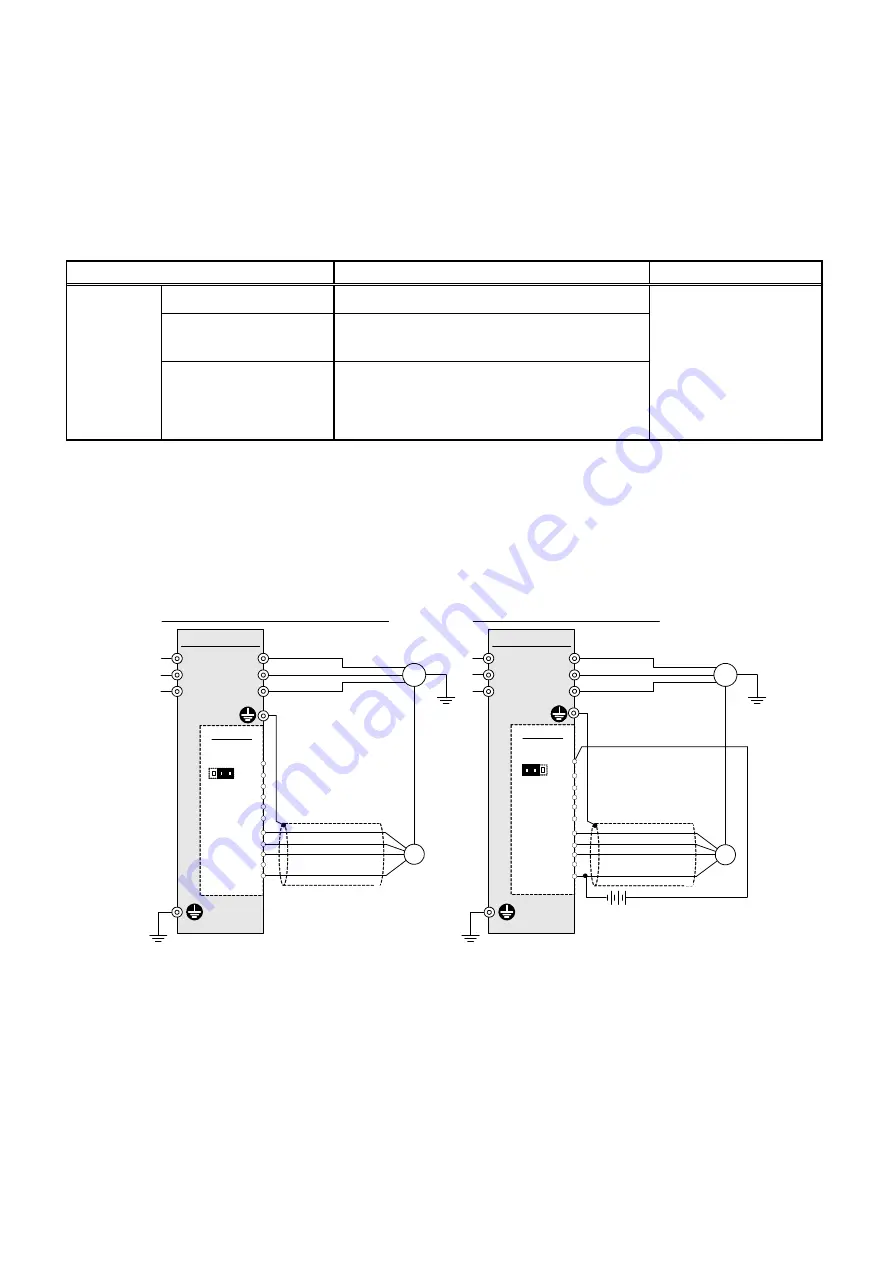
6-2-2. Connection diagram examples
Figure 9 shows the connection diagram example for speed control.
When using inverter internal power supply
OPC-G1-PG
When using external power supply
FRENIC-MEGA
OPC-G1-PG
12 VDC
±
10%/15 VDC
±
10%
FRENIC-MEGA
PO
XA
XB
XZ
PO
CM
YA
YB
YZ
*
2
PI
CM
U
V
W
M
U
V
W
M
L1/R
L2/S
L3/T
PG
PO
XA
XB
XZ
PO
CM
YA
YB
YZ
*
2
PG
PI
CM
G
G
L1/R
L2/S
L3/T
(PGP)
(PA)
(PB)
(PGM)
(PGP)
(PA)
(PB)
(PGM)
*
3
*
3
*
4
*
4
*1
*
1
J1
*
5
EXT INT
J1
*
5
EXT INT
G
G
*1
When a Fuji VG motor exclusively designed for vector control is connected, the signal names in parentheses ( ) apply.
*2 The terminal [YZ] is not used for control. If the PG issues Z phase outputs, there is no need to connect the PG wire to this terminal.
*3 For wiring between the PG and the inverter, use a shielded cable. Basically, the shielded layer should be grounded. If any malfunction occurs
due to noise, however, connecting the shielded layer to the terminal [CM] may reduce the problem.
If the wiring between the PG and the inverter is long, interference of A- and B-phases may cause PG signal malfunctions, resulting in
abnormal noise or torque pulsation. In such a case, minimizing the wiring length (by reviewing the wiring route) or using a cable with a
smaller stray capacitance may reduce the problem.
*4 The terminal SS of the VG motor should be opened.
*5 When using the inverter internal power supply, turn the slide switch J1 on the PG interface card to the INT position; when using an external
power supply, to the EXT position.
Figure 9 Connection Diagrams for Speed Control


