


- 2 -
3. Wiring
In general, the covers of the control signal wires are not specifically designed to withstand a high voltage (i.e., reinforced insulation is
not applied). Therefore, if a control signal wire comes into direct contact with a live conductor of the main circuit, the insulation of the
cover might break down, which would expose the signal wire to a high voltage of the main circuit. Make sure that the control signal
wires will not come into contact with live conductors of the main circuit.
Failure to observe this precaution could cause electric shock or an accident.
Noise may be emitted from the inverter, motor and wires.
Take appropriate measures to prevent the nearby sensors and devices from malfunctioning due to such noise.
An accident could occur.
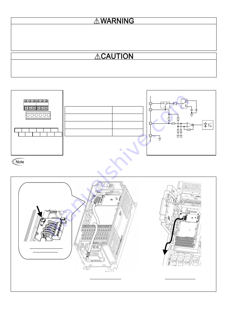
Perform wiring properly, referring to the "Terminal Allocation and Symbol Diagram," "Terminal Specifications," and "Internal Block
Diagram" shown below.
PI
PO
YA
YB
YZ
CM
PI
PO
XA
XB
XZ
CM
Figure 6 Terminal Allocation
and Symbol Diagram
Table 1 Terminal Specifications
Terminal Size
M2
Tightening Torque
0.22 to 0.25 N·m
Recommended Wire Gauge*
AWG16 to 26
Wire strip length
5 mm
* Insulated wires with allowable temperature of 105ºC
(UL-listed) are recommended.
Optocoupler
DC+12V
DC+15V
INT
EXT
+
PO
PI
XA,XB,XZ
YA,YB,YZ
CM
12V
15V
J1
SW1
-
Figure 7 Internal Block Diagram
To prevent malfunctioning due to noise, separate the wires for the PG interface card as far apart as possible from those for the
main circuits. Also, inside the inverter, bundle and fix the wires for the PG interface card so that they do not come into direct
contact with live parts of the main circuits (for example, the main circuit terminal block).
In the case of 0.4 kW
Pass the wires from the PG interface card
between the control circuit terminal block
and the front cover.
In the case of 75 kW
When grounding the shielded
cable, use a crimp ring terminal,
R1.25-3 or the like and fasten it
together with the card using this
screw.
Location for grounding
the shielded cable


