C
hap.
3
O
P
E
R
AT
IO
N
U
S
IN
G
"T
P
-A1
-LM
2"
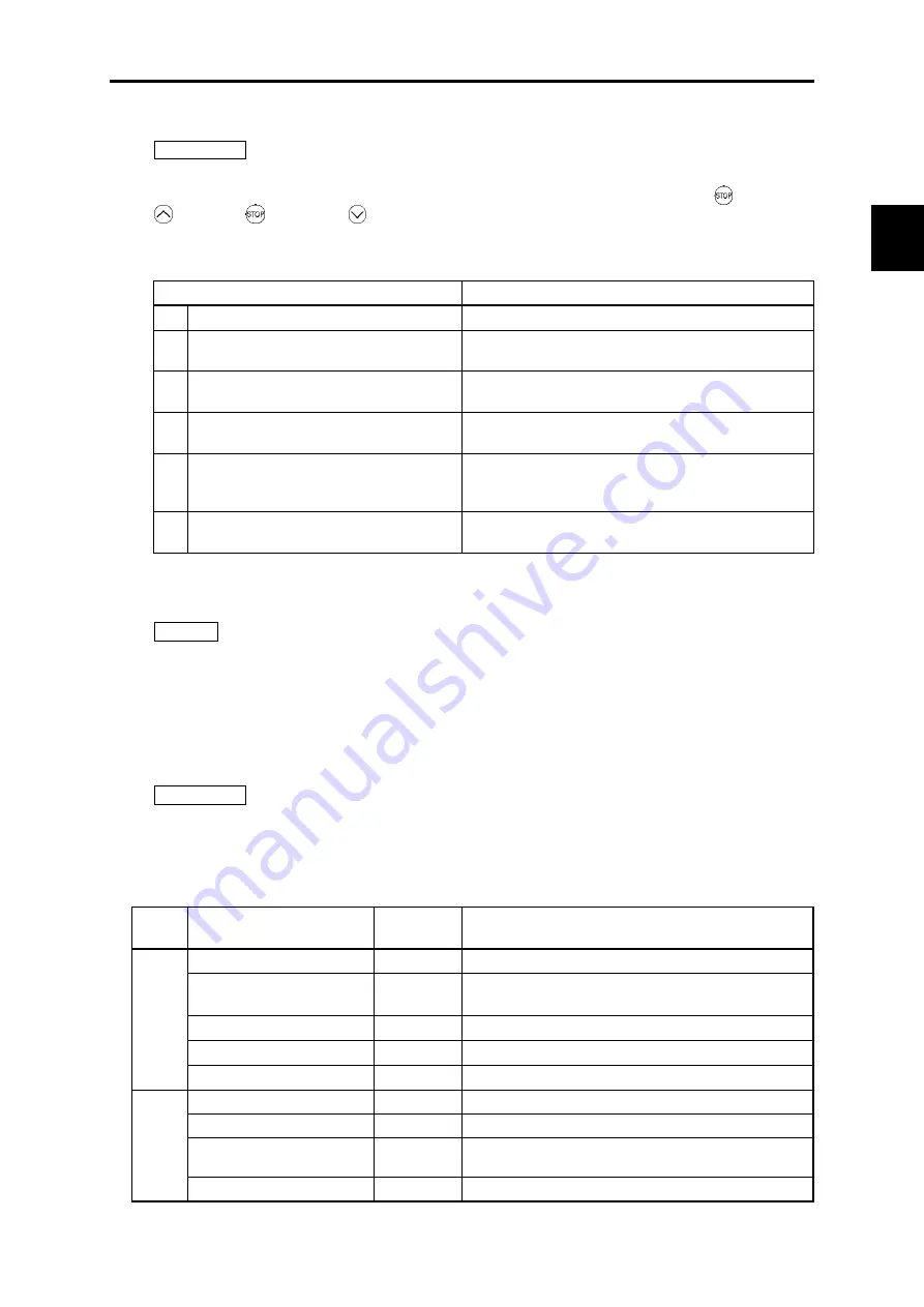
3.4.3.5 Initialize function code data: “Initialize”
PRG > 2 > 5
This returns function code data to the values in the factory default settings or sets function code data
for certain application system. Changing the data requires double-key operation (the key and the
key or the key and the key). The following types of initialization are available.
Table 3.10 Initialization types
Initialization type
Function
0
Manually set values
Does not initialize.
1
Initialize values to factory default values
(vector control for IM)
Initialize all function code data to settings suited for vector
control for IM. (initializes to factory default values).
2
System-specific initialization
(vector control for PMSM)
Initialize all function code data to settings suited for vector
control for PMSM.
3
System-specific initialization
(open loop control for IM)
Initialize all function code data to settings suited for open
loop control for IM.
11 Limited initialization
(initialization except for communication
function codes)
Initialize function codes except communication settings.
12 Limited initialization
(initialization for customizable logic)
Initialize function codes for customizable logic U/U1 codes.
3.4.4 Inverter Information: “INV Info”
PRG > 3
Menu number 3, “INV Info” allows display of various information of the inverter: Current operation status,
i/o status, and maintenance data.
Travel direction counter function is also provided in this menu.
3.4.4.1 Check Operational Status: “Op Monitor”
PRG > 3 > 1
This allows to check the inverter’s operational status. This can be used when confirming operational
status during maintenance or on test runs.
Table 3.11 Display items in “Op Monitor”
Page
No.
Category
Code
Details
1
Reference speed (pre-ramp)
Fref
Reference speed (pre-ramp) currently specified [Hz]
Reference speed (final)
Fout1
Reference speed (final) commanded to the Automatic Speed
Regulator (ASR) [Hz]
Output frequency
Fout2
Frequency being output [Hz]
Motor rotational speed
SyncSp
Detected speed [r/min]
Elevator speed
LiftSp
Detected speed [mm/s]
2
Output current
Iout
Output current value [A]
Output voltage
Vout
Output voltage value [V]
Calculated torque
Torque
Calculated torque [%] based on the motor rated torque being
at 100%. *1
Power consumption
Power
Power consumption [kW]
3-19
Summary of Contents for Frenic lift
Page 1: ...LM2A series Reference Manual INR SI47 1909a E...
Page 7: ......
Page 13: ......
Page 51: ...2 38...
Page 221: ......
Page 252: ......
Page 254: ...URL http www fujielectric com...


