26
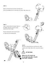
STEP 5
Remove 2 Allen screws (12) from main frame (01).
Fix front handlebars (04) on main frame (01) using 2 Allen screws (12).
STEP 6
Attach computer (08) to computer holder on
handlebars (04) and connect the upper
sensor wire (19) as shown.
Plug the hand pulse wire (18) into the jack
on the back of the computer (08).
STEP 7
Remove 2 screws (82) from main frame (01), attach
remote-control holder (89) and fix it using the 2 screws
(82).
ATTENTION!
Make sure all screws are
firmly tightened after all parts
have been installed.
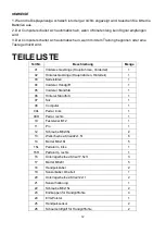
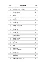
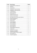
Summary of Contents for HT 200
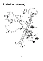
Page 15: ...15 Explosionszeichnung...
Page 16: ...16...
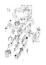
Page 33: ...33 EXPLODED VIEW...
Page 34: ...34...

