background image

10

FE44 

ELLIPTICAL

#78. M5 x 10mm  

Phillips Head Screw 

(4 pcs)
#79. M5 x 15mm 

Phillips Head Screw 

(8 pcs)

4

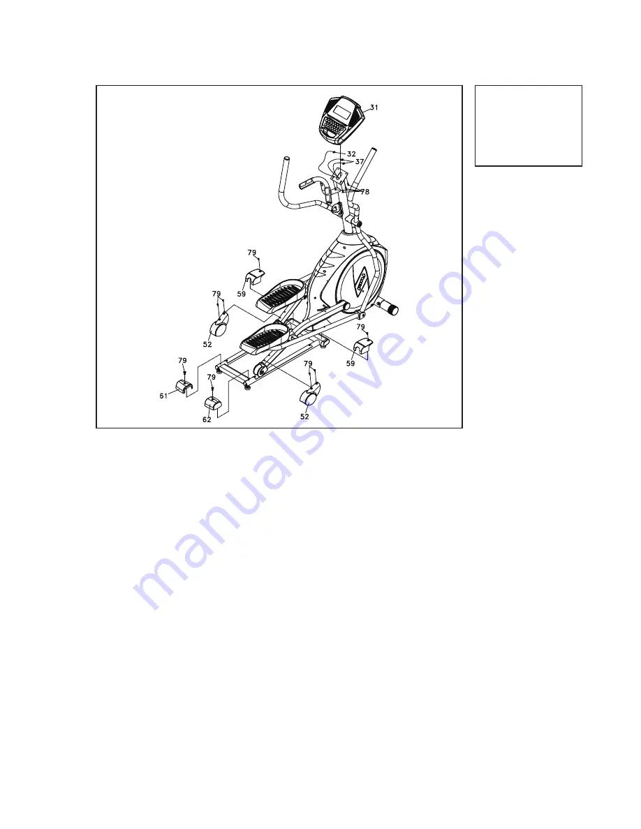
Hardware Step 4

1.  Locate the Console Assembly (31) and the four Phillips Head Screws (78) by 

using the Phillips Head Screw Driver (110).

2.  There will be two electrical wire connectors at the top opening of the Console 

Mast (10), two Handpulse W/Cable Assemblies (37), one Computer Cable 

(32). Connect these to the mating connectors on the back of the Console As-

sembly (31). The connectors are keyed so you cannot plug them in the wrong 

way so do not force them.

3.  Storing the excess wire back into the Console Mast (10), carefully install the 

Console Assembly (31) onto the mounting plate of Console Mast (10) and 

secure using the four Phillips Head Screws (78)

4.  Install the two pcs of Slide Wheel Covers (52) and the four Phillips Head 

Screws (79) by using the Phillips Head Screw Driver (110).

5.  Use one Phillips Head Screw (79) to secure Rear Stabilizer Cover (L) (61) on 

the Pedal Arm (L) and Rail Tube with Phillips Head Screw Driver (110). Repeat 

the procedure for Rear Stabilizer Cover (R) (62) for the other side.

6.  Use two Phillips Head Screw (79) to secure Middle Stabilizer Cover (59) on the 

Pedal Arm (L.R) and Rail Tube with Phillips Head Screw Driver (110). 

PLASTIC COVERS

Note: Use the M5 Allen Wrench/Phillips Head Screw Driver (108) to tighten hardware in this step.

Summary of Contents for FE44

Page 1: ...FE44 ELLIPTICAL OWNER S MANUAL PLEASE CAREFULLY READ THIS ENTIRE MANUAL BEFORE OPERATING YOUR NEW ELLIPTICAL...

Page 2: ...ON ANY OTHER APPLICATION VOIDS THIS WARRANTY IN ITS ENTIRETY Product Registration Important Safety Instructions Important Electrical Instructions Important Operation Instructions FE44 Assembly Instruc...

Page 3: ...experience as pleasant as possible for many years to come If you have questions or if parts are missing or damaged or you require customer service call 1 866 697 6531 Please have your model number and...

Page 4: ...ck or injury to persons 1 An appliance should never be left unattended when plugged in Unplug from outlet when not in use and before putting on or taking off parts 2 Do not operate under blanket or pi...

Page 5: ...your elliptical during an electrical storm Surges may occur in your household power supply that could damage elliptical components Use caution while participating in other activities while using your...

Page 6: ...Flat Washer 2 pcs 120 3 8 x 23 x 2T Curved Washer 4 pcs 147 8 5 26 2 0T Flat Washer 2 pcs 151 5 16 15mm Button Head Socket Bolt 2 pcs 121 3 8 x 3 4 Hex Head Bolt 1 pc 150 3 8 x 12 5T Cap Nut 2 pcs 148...

Page 7: ...16 x 15mm Hex Head Bolt 6 pcs 79 M5 x 15mm Philips Head Screw 8 pcs 78 M5 x 10mm Phillips Head Screw 4 pcs 108 M5 Allen Wrench Phillips Head Screw Driver 111 12 14mm Wrench 113 12mm Wrench 110 Philli...

Page 8: ...t Put two Flat Washers 94 two Split Washers 120 onto the two Hex Head Bolts 119 Install and hand tighten by using the 12 14m m Wrench 111 4 NOTE There is a electrical wire running through the Console...

Page 9: ...FE44 ELLIPTICAL 7 CONSOLE MAST CONSOLE 1...

Page 10: ...ase and take apart Pedal Axle 17 on left Pedal Arm 2 and install left Connecting Arm 7 onto left Pedal Arm Tighten the screw together with the previously released Pedal Axle with 12mm and 14mm open en...

Page 11: ...x 23 x 1 5T Curved Washer 6 pcs 3 Hardware Step 3 1 Install the Left and Right Swing Arms 13 14 into the Lower Left and Right Lower Handle Bars 4 5 with six Hex Head Bolts 70 and six Curved Wash ers 1...

Page 12: ...ss wire back into the Console Mast 10 carefully install the Console Assembly 31 onto the mounting plate of Console Mast 10 and secure using the four Phillips Head Screws 78 4 Install the two pcs of Sl...

Page 13: ...r shows how many virtual miles the elliptical has gone The Time Window shows how many total hours the elliptical has been used The odometer and time will remain displayed for only a few seconds then t...

Page 14: ...your workout this is a great feature To resume your workout during Pause just press the Start key If the Stop button is pressed twice during a workout the program will end and a Workout Sum mary is d...

Page 15: ...aintenance Menu may be called Engineering Mode depending on version press and hold down the Start Stop and Enter keys keep holding the keys down for about 5 seconds and the Message Window will display...

Page 16: ...sage Window will show a summary of your workout The summary will be displayed for a short time then the console will return to the startup display MANUAL PROGRAM 1 Press Program key then press the Ent...

Page 17: ...s designed to increase your cardiovascular function and endurance This is exercise for your heart and lungs It will build up your heart muscle and increase blood flow and lung capacity This is achieve...

Page 18: ...delete the current program if you want to build a new one 3 The Message Window will ask you to enter your Age You may enter your age using the Level UP DOWN keys then press the Enter key to accept th...

Page 19: ...ns fat while 80 is for strengthening the cardio vascular system This 60 to 80 is the zone to stay in for maximum benefit For someone who is 40 years old their predicted target heart rate zone is calcu...

Page 20: ...n of Effort 6 Minimal 7 Very very light 8 Very very light 9 Very light 10 Very light 11 Fairly light 12 Comfortable 13 Somewhat hard 14 Somewhat hard 15 Hard 16 Hard 17 Very hard 18 Very hard 19 Very...

Page 21: ...de Press the Enter key to access the menu below Press the Level Up Down keys to navigate the menu A Key Test Will allow you to test all the keys to make sure they are functioning B Display Test Automa...

Page 22: ...es use of parts other than original FUEL acts of God 4 Products with original serial numbers that have been removed or altered 5 Products that have been sold transferred bartered or given to a third p...

Page 23: ......

Page 24: ...www fuelfitnessusa com 2014 All RIghts Reserved FE44 Owner s Manual...

Reviews: