CAP-600
2
INSTALLATION
CONGRATULATIONS
on your new Curtis
Challenge Air Compressor. Please examine the
compressor for shipping damage(s) and if any are
found report it immediately to the carrier.
Select a clean dry location with a rigid floor strong
enough to support the compressor. If the
compressor is to be located in an area where
vibration is critical, properly engineered vibration
mounts and flexible piping should be used.
Remove the skid.
NOTE: The compressor should
never be operated on the shipping skid.
Level
the compressor so it can be bolted down securely.
Before tightening the bolts, check to see that all
four feet are resting on the foundation. Shim as
necessary to eliminate stress on the receiver or
base when the bolts are tightened. We suggest
using a level for proper alignment.
Maximum ambient temperature in which the
compressor and motor should be operated is
104
°
F. Therefore, adequate ventilation must be
provided.
The suction openings of the compressor are
equipped with a combination air filter-muffler to
protect the compressor from normal dust and other
harmful substances. If the air around the
compressor is excessively hot, dusty, humid or
contaminated with foreign gases (such as ammonia
or acid fumes) move the filter-muffler to a remote
point where the air is clean, cool and dry. Run a
pipe to the compressor suction opening. If the run
is over 50 feet in length, use a larger pipe to avoid
excessive pressure drop. In order to fit the filter to
the compressor, bush down the connections. Be
sure piping and fittings are clean and free from dirt
and chips. If the filter is installed outside, check to
insure that it is located above the normal outside
dust level, and that rain cannot enter the filter
element. Where the relocation of the filter-muffler
is not possible or feasible, an oil bath filter is
recommended and is available from Curtis.
On basic or base mounted compressors run a
discharge pipe to the receiver or optional
aftercooler and bush up or down as necessary.
The pipe should enter near the top of the receiver.
Keep in mind that condensate may form in the
discharge line; therefore, the lines should always
be pitched to drain condensate away from the
compressor. Always provide a safety relief valve in
the discharge line between the compressor and in-
line shutoff valves. If more than one compressor
pumps into a common system, a check valve in the
discharge line of each compressor is recommended
to prevent moisture from entering the cylinder head
when one compressor is idle. A globe or gate valve
installed in the discharge line will allow compressor
isolation from plant air system for compressor
maintenance. (Note: A safety relief valve should be
located between the compressor and the
globe/gate valve.)
Check the electrical supply for voltage, phase, and
frequency to see that they match the nameplate
stampings on the motor, magnetic starter,
solenoids, and other controls. Use electrical wires
of adequate size to carry the full load current of the
motor without excessive voltage drop. Charts are
available from Curtis (upon request) to provide
information on this. The motor must always be
protected by
a starter with properly sized thermal
overload(s). The starter should protect the motor
from overheating and burnout due to an overload,
low voltage or single phasing of a 3-phase circuit.
Failure to install the proper starter and
overloads will void the motor manufacturers
warranty.
Follow the National Electric Code or
local electric code in providing wiring, fusing and
disconnect switches.
NOTE: Do not close the
disconnect switch to start the compressor until
the procedures outlined under "Startup
Procedures" have been completed.
LIMITED SAFETY PRECAUTIONS
(Also see supplement LV-474)
The following safety precautions are recommended
in the use of this compressor:
1. Use a totally enclosed OSHA-approved belt
guard to cover the drive assembly. Where
possible, place the flywheel toward the wall, and
mount the unit a minimum distance of 2 feet from
the wall for maintenance convenience.
2. Turn off & lock out the electrical disconnect
switch before working on the unit to prevent the
unit from starting unexpectedly
3. Release all air pressure from the system before
working on the unit and red tag all electrical
control switches, for safety precaution.
4. Do not by-pass motor over-current protection.
5. Do not change the setting or in any way affect
the operation of the safety valve.
6. Keep unit securely anchored so that movement
will not put a strain on piping, wiring, or air
receiver.
WARNING: Read and understand supplement LV-474 before installing and operating the compressor.
Summary of Contents for CA series
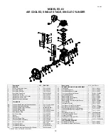
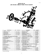
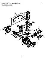
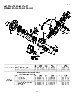
Page 12: ...CAP 600 12 AIR COOLED SINGLE STAGE MODELS ES 05 ES 10 ES 20 ...
Page 20: ...CAP 600 AIR COOLED SINGLE STAGE MODEL ES 150A 18 ...
Page 22: ...CAP 600 AIR COOLED SINGLE STAGE MODEL ES 150B 18A ...
Page 24: ...CAP 600 20 AIR COOLED TWO STAGE MODELS E 11 E 23 ...
Page 30: ...CAP 600 AIR COOLED TWO STAGE MODEL E 25 25A ...
Page 34: ...CAP 600 26 AIR COOLED TWO STAGE MODEL E 35 ...
Page 36: ...AIR COOLED TWO STAGE MODEL E 57 E57A CAP600 28 ...
Page 39: ...CAP 600 31 VALVE PLATES DESIGNS FOR E 57 COMPRESSOR ...
Page 47: ...CAP 600 NOTES 39 ...


