background image

15

DE

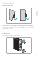
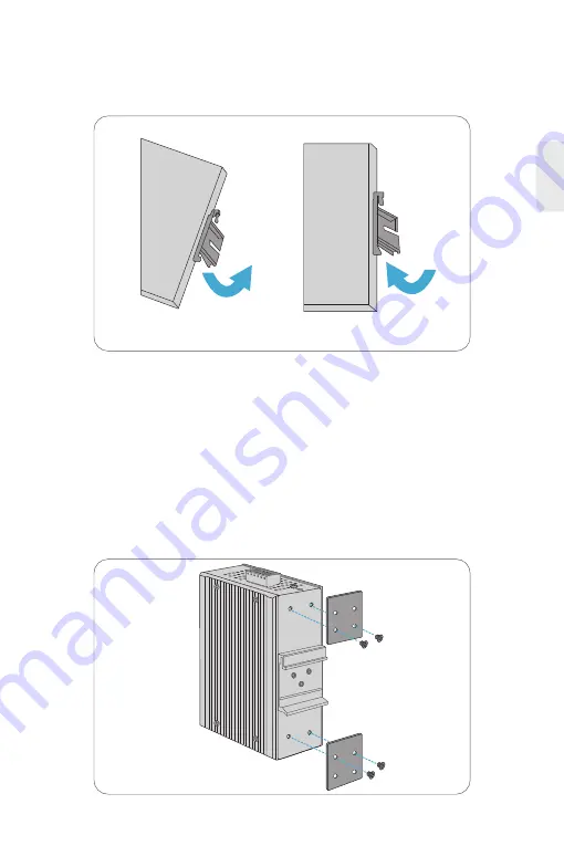
1. Positionieren Sie das Gerät vor der DIN-Hutschiene und haken Sie die Montagehalterung über der 
Oberseite der Hutschiene ein.

Montage des Switches

Schrauben Sie die Montagehalterung am Switch mit M3-Schrauben fest.

Montage für DIN-Hutschiene

Wandmontage

Gerät montieren

Gerät entfernen

2. Drehen Sie den Switch nach unten in Richtung der Hutschiene, um ihn zu verriegeln. Wenn Sie ein 
Klicken hören, ist der Switch fest in der Hutschiene.

3. Um das Gerät zu entfernen, ziehen Sie es nach unten, um die Unterseite der DIN-Hutschiene 
freizugeben, und drehen Sie es von der Hutschiene weg.

Summary of Contents for IES3110-8TF

Page 1: ... SWITCH SWITCH INDUSTRIEL MANAGEABLE L2 Quick Start Guide V1 0 Quick Start Anleitung Guide de Démarrage Rapide IES3110 8TF Switch P1 FAULT RESET P2 9 9 10 10 7 5 3 1 2 4 6 8 R O RING 1G 2 5G Link Act 1G 2 5G SFP Link Act IES3110 8TF Link Act 1000 Act Link ...

Page 2: ...the switch and describes how to deploy the switch in your network 1 EN Mounting Bracket x2 M3 Screw x4 NOTE IES3110 8TF switch has dust plugs delivered with it Keep the dust plugs properly and use them to protect idle ports P1 FAULT RESET P2 9 9 10 10 7 5 3 1 2 4 6 8 R O RING 1G 2 5G Link Act 1G 2 5G SFP Link Act IES3110 8TF Link Act 1000 Act Link ...

Page 3: ...LT RESET P2 9 9 10 10 7 5 3 1 2 4 6 8 R O RING 1G 2 5G Link Act 1G 2 5G SFP Link Act IES3110 8TF Link Act 1000 Act Link Front Panel Ports Upper Panel Hardware Overview 8x 10 100 1000BASE T Ports 2 EN Ports Description 10 100 1000BASE T ports for Ethernet connection SFP ports for 100M 1G 2 5G connection RJ45 SFP Grounding Point Terminal Block Connector ...

Page 4: ...Rear Panel 3 EN Front Panel LEDs DIN rail Mounting Kit P1 FAULT RESET P2 9 9 10 10 7 5 3 1 2 4 6 8 R O RING 1G 2 5G Link Act 1G 2 5G SFP Link Act IES3110 8TF Link Act 1000 Act Link SFP RJ45 SYS ...

Page 5: ...hat the port is successfully connecting to the network at 1000Mbps Indicates that the port is successfully connecting to the network at 10Mbps or 100Mbps LINK ACT 1000 Green Light Blink Orange Light Off SFP Indicates the link through that port is successfully established Indicates that the Switch is actively sending or receiving data over that port Indicates that the port is successfully connectin...

Page 6: ...owards the rail to lock it into place You will know it is secure when you hear the click 3 To remove the unit pull down to clear the bottom of the DIN Rail and rotate away from the rail Mounting the Switch Screw on the mounting bracket on the switch with M3 screws DIN Rail Mounting Wall Mounting Mounting the unit Releasing the unit ...

Page 7: ... follow the steps below to insert the power wire 1 Insert positive negative AC or DC power wires into Contacts 1 and 2 for Power 1 or Contacts 5 and 6 for Power 2 Connecting the Power NOTE This product is intended to be mounted to a well grounded mounting surface such as a metal panel Grounding and wire routing help limit the effects of noise due to electromagnetic interference EMI Run the ground ...

Page 8: ...nal block should be in the range from 12 to 24 AWG Pin 2 6 Positive Pin Negative Pin Pin 1 5 2 Tighten the wire clamp screws for preventing the wires from loosening Live line Positive Null line Negative Requiring good ground connection Name No Description V1 V2 V1 V2 1 2 3 ...

Page 9: ...Link Act 1000 Act Link 8 EN 1 Plug the compatible SFP transceiver into the SFP port 2 Connect a fiber optic cable to the fiber transceiver Then connect the other end of the cable to another fiber device Connecting the SFP Ports 1 Connect an Ethernet cable to the RJ45 port of a camera outdoor AP computer or other network device 2 Connect the other end of the Ethernet cable to the RJ45 port of the s...

Page 10: ...to or forced rate Connecting the Switch Remotely Unsuccessfully 1 Test network connectivity through ping 2 If the network is reachable try restarting the switch 3 Check if the corresponding service is enabled The Port is not Working the LED Indicator is Off 1 Ensure the switch ports are in the no shutdown state 2 Check if the switch can read the DDM information 3 Check if the port speed setting is...

Page 11: ...y Warranty IES3110 8TF switch enjoy 5 years limited warranty against defect in materials or workmanship For more details about warranty please check at https www fs com policies warranty html Return If you want to return item s information on how to return can be found at https www fs com policies day_return_policy html 5 Download https www fs com products_support html Help Center https www fs com...

Page 12: ...ie Sie den Switch in Ihrem Netzwerk einsetzen 11 DE Montagehalterung x2 M3 Schraube x4 Hinweis Beim Switch IES3100 8TF werden Staubschutzkappen mitgeliefert Bewahren Sie die Staubschutzkappen ordnungsgemäß auf und verwenden Sie sie zum Schutz ungenutzter optischer Ports P1 FAULT RESET P2 9 9 10 10 7 5 3 1 2 4 6 8 R O RING 1G 2 5G Link Act 1G 2 5G SFP Link Act IES3110 8TF Link Act 1000 Act Link ...

Page 13: ...ET P2 9 9 10 10 7 5 3 1 2 4 6 8 R O RING 1G 2 5G Link Act 1G 2 5G SFP Link Act IES3110 8TF Link Act 1000 Act Link Ports an der Vorderseite Obere Platte Hardware Übersicht 8x 10 100 1000BASE T Ports 12 DE Ports Beschreibung 10 100 1000BASE T Ports für Ethernet Verbindung SFP Ports für 100M 1G 2 5G Verbindung RJ45 SFP Erdungspunkt Anschlussklemmen Blockstecker ...

Page 14: ...platte 13 DE LEDs an der Vorderseite Montagekit für DIN Hutschiene P1 FAULT RESET P2 9 9 10 10 7 5 3 1 2 4 6 8 R O RING 1G 2 5G Link Act 1G 2 5G SFP Link Act IES3110 8TF Link Act 1000 Act Link SFP RJ45 SYS ...

Page 15: ...ann die Daten durch den Port senden oder erhalten Der Port verbindet erfolgreich mit dem Netzwerk von 100Mbps Der Port verbindet erfolgreich mit dem Netzwerk von 10Mbps oder 100Mbps Die Verknüpfungen zu den Port werden erfolgreich etabliert Switch kann die Daten durch den Port senden oder erhalten Der Port verbindet erfolgreich mit dem Netzwerk von 1000 Mbps Der Port verbindet erfolgreich mit dem ...

Page 16: ... Switch mit M3 Schrauben fest Montage für DIN Hutschiene Wandmontage Gerät montieren Gerät entfernen 2 Drehen Sie den Switch nach unten in Richtung der Hutschiene um ihn zu verriegeln Wenn Sie ein Klicken hören ist der Switch fest in der Hutschiene 3 Um das Gerät zu entfernen ziehen Sie es nach unten um die Unterseite der DIN Hutschiene freizugeben und drehen Sie es von der Hutschiene weg ...

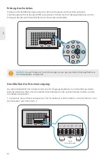
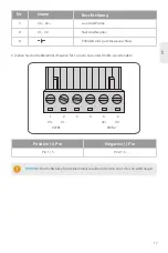
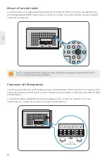
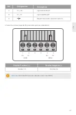
Page 17: ...Klemmenblockanschluss mit 6 Kontakten Bitte befolgen Sie die nachstehenden Schritte um das Stromkabel einzuführen 1 Stecken Sie die positiven negativen AC DC Stromkabel in die Kontakte 1 und 2 für Strom 1 oder die Kontakte 5 und 6 für Strom 2 Anschließen der Stromversorgung HINWEIS Dieses Produkt ist für die Montage an einer gut geerdeten Montagefläche wie einer Metallplatte vorgesehen Erdung und ...

Page 18: ...eiste sollte im Bereich von 12 bis 24 AWG liegen Pin 2 6 Positive Pin Negative Pin Pin 1 5 2 Ziehen Sie die Drahtklemmschrauben fest um ein Lösen der Drähte zu verhindern Live Line Positiv Null Line Negativ Erfordert eine gute Masseanschluss Name Nr Beschreibung V1 V2 V1 V2 1 2 3 ...

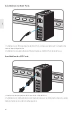
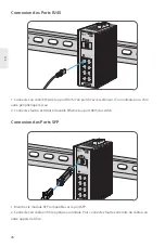
Page 19: ...1 Stecken Sie den kompatiblen SFP Transceiver in den SFP Port 2 Schließen Sie ein Glasfaserkabel an den Glasfasertransceiver an Schließen Sie dann das andere Ende des Kabels an ein anderes Glasfasergerät an Anschließen der SFP Ports 1 Schließen Sie ein Ethernet Kabel an den RJ45 Port von Kamera Outdoor AP Computer oder anderen Netzwerkgeräten an 2 Schließen Sie das andere Ende des Ethernet Kabels ...

Page 20: ...erzwungen ist Fehlgeschlagener Fernanschluss des Switches 1 Testen Sie die Netzwerkkonnektivität durch Ping 2 Wenn das Netzwerk erreichbar ist versuchen Sie den Switch neu zu starten 3 Prüfen Sie ob der entsprechende Dienst aktiviert ist Der Port funktioniert nicht die LED Anzeige ist aus 1 Vergewissern Sie sich dass die Ports des Switches nicht heruntergefahren sind 2 Prüfen Sie ob der Switch die...

Page 21: ...uktgarantie Garantie IES3110 8TF Switch gilt eine beschränkte Garantie von 5 Jahren auf Material und Verarbeitungsfehler Weitere Einzelheiten zur Garantie finden Sie unter https www fs com de policies warranty html Rückgabe Wenn Sie Artikel zurückgeben möchten finden Sie Informationen über die Rückgabe unter https www fs com de policies day_return_policy html 5 Download https www fs com de product...

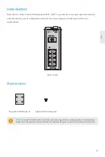
Page 22: ...ndiquer comment procéder à son déploiement 21 FR Support de Montage x2 Support de Montage x2 NOTE Le switch IES3110 8TF est livré avec des capuchons anti poussière Conservez les capuchons de poussière correctement et utilisez les pour la protection des ports inactifs P1 FAULT RESET P2 9 9 10 10 7 5 3 1 2 4 6 8 R O RING 1G 2 5G Link Act 1G 2 5G SFP Link Act IES3110 8TF Link Act 1000 Act Link ...

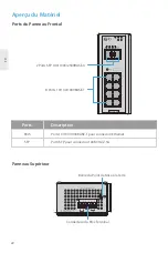
Page 23: ... 10 7 5 3 1 2 4 6 8 R O RING 1G 2 5G Link Act 1G 2 5G SFP Link Act IES3110 8TF Link Act 1000 Act Link Ports du Panneau Frontal Panneau Supérieur Aperçu du Matériel 8 Ports 10 100 1000BASE T 22 FR Ports Description Ports 10 100 1000BASE T pour connexion Ethernet Ports SFP pour connexion 100M 1G 2 5G RJ45 SFP Borne du Point de Mise à la Terre Connecteur du Bloc Terminal ...

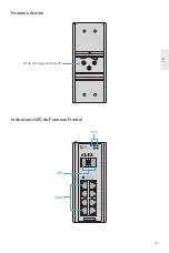
Page 24: ...rière 23 FR Indicateurs LED du Panneau Frontal Kit de Montage de Rail DIN P1 FAULT RESET P2 9 9 10 10 7 5 3 1 2 4 6 8 R O RING 1G 2 5G Link Act 1G 2 5G SFP Link Act IES3110 8TF Link Act 1000 Act Link SFP RJ45 SYS ...

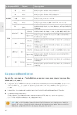
Page 25: ...rt se connecte avec succès au réseau à 1000Mbps Indique que le port se connecte avec succès au réseau à 10Mbps ou 100Mbps LINK ACT 1000 Vert Allumé Clignotant Orange Allumé Éteint SFP Indique que le lien avec ce port a été établi avec succès Indique que le Switch envoie ou reçoit activement des données sur ce port Indique que le port se connecte avec succès au réseau à 1000Mbps Indique que le port...

Page 26: ... verrouiller en place Vous saurez qu il est bien fixé lorsque vous entendrez un clic 3 Pour retirer l appareil tirez vers le bas pour dégager le bas du rail DIN et faites pivoter pour l éloigner du rail Montage du Switch Vissez le support de montage sur le switch avec des vis M3 Montage sur Rails DIN Montage Mural Montage de l unité Retrait de l unité ...

Page 27: ... terminal avec 6 contacts Veuillez suivre les étapes ci dessous pour insérer le câble d alimentation 1 Insérez les câbles d alimentation positive négative CA ou CC dans les contacts 1 et 2 pour l alimentation 1 ou dans les contacts 5 et 6 pour l alimentation 2 Connexion de l Alimentation NOTE Ce produit doit être installé sur une surface de montage correctement mise à la terre comme un panneau mét...

Page 28: ...t être entre 12 et 24AWG Broches 2 6 Broche Positive Broche Négative Broches 1 5 2 Serrez les vis de serrage des fils pour éviter qu ils ne se desserrent Ligne directe Positif Ligne nulle Négatif Requiert une bonne connexion à la terre Désignation No Description V1 V2 V1 V2 1 2 3 ...

Page 29: ...Act 1000 Act Link 28 FR 1 Branchez le module SFP compatible sur le port SFP 2 Connectez un câble en fibre optique au module Puis connectez l autre extrémité du câble à un autre appareil à fibre Connexion des Ports SFP 1 Connectez un câble Ethernet au port RJ45 d un point d accès extérieur d un ordinateur ou d un autre périphérique réseau 2 Connectez l autre extrémité du câble Ethernet au port RJ45...

Page 30: ...nication est le débit automatique ou forcé Échec de la Connexion à Distance du Switch 1 Testez la connectivité du réseau par ping 2 Si le réseau est accessible essayez de redémarrer le switch 3 Vérifiez si le service correspondant est activé Le Port ne Fonctionne pas l Indicateur LED est Éteint 1 Assurez vous que les ports du switch sont dans l état no shutdown 2 Vérifiez si le switch est capable ...

Page 31: ...F bénéficie d une garantie limitée de 5 ans contre tout défaut matériel ou de fabrication Pour plus de détails sur la garantie veuillez consulter la page https www fs com fr policies warranty html Retour Si vous souhaitez retourner un ou plusieurs articles vous trouverez des informations sur la procédure de retour à l adresse suivante https www fs com fr policies day_return_policy html 5 Télécharg...

Page 32: ... Operation of this equipment in a residential area is likely to cause harmful interference in which case the user will be required to correct the interference at his own expense This device complies with part 15 of the FCC Rules Operation is subject to the following two conditions 1 This device may not cause harmful interference and 2 this device must accept any interference received including int...

Page 33: ...me à la Directive 2014 30 UE Une copie de la Déclaration UE de Conformité est disponible sur https www fs com fr company quality_control html Die FS COM GmbH erklärt hiermit dass dieses Gerät mit der Richtlinie 2014 30 EU konform ist Eine Kopie der EU Konformitätserklärung finden Sie unter www fs com de company quality_control html FS COM GmbH hereby declares that this device is in compliance with...

Reviews: