FS 108718 Quick Start Manual Download Page 13

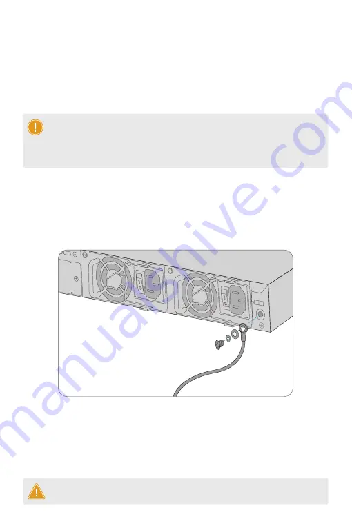
Grounding the Switch

1

Power

2

Input 

Module2

Output 

Input 

Output 

1. Connect one end of the grounding cable to a proper earth ground, such as the rack in which the 
switch is mounted.
2. Secure the grounding lug to the grounding point on the switch back panel with the washers and 
screws.

CAUTION:


The earth connection must not be removed unless all supply connections have 

been disconnected.

2. Remove the old power module and take the plane printed with power information as the top panel
of the power module. Hold the handle of the power module with one hand, and hold the end of the 
power module with the other hand. Insert it into the chassis along the guide rail uprightly and 
slowly until it clicks into place, and make sure that it is in good contact with the power slot.

1. Take a new power module out of the package and confirm the input mode and the input 
parameters of the power module match the requirements.

NOTE:


1. S3410-10TF-P switch has one built-in power supply.

2. Insert the power module steadily. Please pay attention to the direction of the power

panel to avoid wrong insertion. If the position is not proper, press the plug of the power

module and hold on to the module handle with one hand to pull it out slowly, then

re-insert it.

Module1

Summary of Contents for 108718

Page 1: ...S3410 Series Switches Quick Start Guide MANAGED L2 GIGABIT POE SWITCHES...

Page 2: ...h and describes how to deploy the switch in your network Grounding Cable x1 Power Cord x1 M4 Screw x6 Rubber Pad x4 Mounting Bracket x2 PoE STATUS M1 M2 PWR1 PWR2 PoE 1 2 3 4 5 6 7 8 9 10 11 12 13 14...

Page 3: ...otect idle optical ports S3410 10TF P Grounding Cable x1 Power Cord x2 M4 Screw x8 Rubber Pad x4 Mounting Bracket x2 S3410 24TS P S3410 48TS P Front Panel Ports Ports Description RJ45 SFP CONSOLE 10 1...

Page 4: ...hernet connection One RJ45 port and one SFP slot with one port active at a time SFP ports for 1 10G connection S3410 24TS P CONSOLE USB RJ45 RJ45 SFP Combo SFP PoE STATUS M1 M2 PWR1 PWR2 PoE 1 2 3 4 5...

Page 5: ...ink Flashing ACT PoE LED Green Good Supply Yellow Over Load CONSOLE SFP S3410 24TS P PoE PoE PoE RESET S3410 48TS P PoE Button Description PoE RESET Switch the display mode between PoE mode and switch...

Page 6: ...TS P S3410 48TS P Dual Power Supplies Expansion Module Slot Grounding Point Front Panel LEDs Power Supply Cable Clamps Holes Grounding Point S3410 10TF P STATUS PoE RJ45 PoE 1 8 SFP 1 Power 2 Input Mo...

Page 7: ...18 19 20 21 22 23 24 24 25 26 23 Green 1000M Yellow 10 100M On Link Flashing ACT PoE LED Green Good Supply Yellow Over Load CONSOLE SFP S3410 24TS P PoE RJ45 PoE 1 24 STATUS M1 M2 PWR1 PoE PWR2 SFP S...

Page 8: ...tion Status SFP Off Solid Green Solid Yellow Solid Yellow Blinking Yellow Off The port is not connected The port is not connected Solid Green The port is connected at 1000 Mbps Blinking Green Off Soli...

Page 9: ...perature of 50 C The installation site must be free from leaking or dripping water heavy dew and humidity Ensure rack and working platforms are well earthed Standard sized 19 wide rack with a minimum...

Page 10: ...4 5 6 7 8 9 10 11 12 13 14 15 16 17 18 19 20 21 22 23 24 24 25 26 23 Green 1000M Yellow 10 100M On Link Flashing ACT PoE LED Green Good Supply Yellow O ver Load CONSOLE SFP S3410 24TS P PoE Mounting t...

Page 11: ...the switch to the rack using four M6 screws and cage nuts SYS 24 25 26 SFP C3440 24T2F2SP PoE Wall Mounting 1 Secure the mounting brackets to the two sides of the switch with the supplied M4 screws 27...

Page 12: ...Input Output PoE Status M1 M2 PWR1 PWR2 PoE 1 2 3 4 5 6 7 8 9 10 11 12 13 14 15 16 17 18 19 20 21 22 23 24 24 25 26 23 Green 10 00M Yellow 1 0 100M On Link Flashing ACT PoE LED Gree n Good Supply Yell...

Page 13: ...the power module with one hand and hold the end of the power module with the other hand Insert it into the chassis along the guide rail uprightly and slowly until it clicks into place and make sure t...

Page 14: ...Input Module2 Output Input Output PoE STATUS M1 M2 PWR1 PWR2 PoE 1 2 3 4 5 6 7 8 9 10 11 12 13 14 15 16 17 18 19 20 21 22 23 24 24 25 23 Green 1000M Yellow 10 100M On Link Flashing ACT PoE LED Green G...

Page 15: ...er end of the cable to another fiber device WARNING Laser beams will cause eye damage Do not look into bores of optical modules or optical fibers without eye protection Connecting the SFP SFP Ports 1...

Page 16: ...od Supply Yellow Over Load CONSOLE SFP S3410 24TS P PoE PoE STATUS M1 M2 PWR1 PWR2 PoE 1 2 3 4 5 6 7 8 9 10 11 12 13 14 15 16 17 18 19 20 21 22 23 24 24 25 26 23 Green 1000M Yellow 10 100M On Link Fla...

Page 17: ...or ts this capability O ther wise you need to ask your network administrator for the appropriate IP settings Internet Protocol Version 4 TCP IPv4 Properties Use the following IP address Obtain an IP a...

Page 18: ...to the switch 2 Check that the parameter configuration of the serial port matches that specified in the instructions 1 10G Port is not Working In the case of compatible cables and transceivers the por...

Page 19: ...port is not in connectivity or it is erroneous in receiving transmitting frames Support and Other Resources Download Help Center Contact Us https www fs com download html https www fs com service help...

Reviews: