background image

3

Do not use the functions described until
you have thoroughly read and under-
stood the following documents:
-

these operating instructions

-

all the operating instructions for the
system components, especially the
safety rules

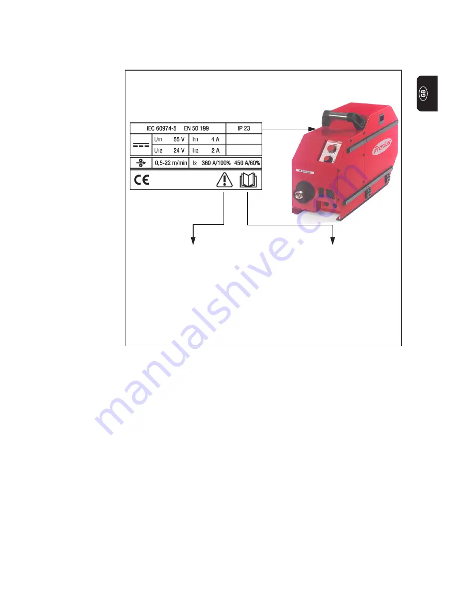
Warning notices on the wire-feed unit VR 4000 Yard

Warning notices
affixed to the
device

The Yard wire-feed unit has safety symbols on the rating plate. The safety symbols
must NOT be removed or painted over. The symbols warn against operating the equip-
ment incorrectly, as this may result in serious injury and damage.

Welding is dangerous. The following
basic requirements must be met:
-

Welders must be sufficiently quali-
fied

-

Suitable protective equipment

-

Keep all persons not involved in the
welding process at a safe distance

Summary of Contents for VR 4000 Yard

Page 1: ...VR 4000 Yard Operating Instructions Spare Parts List Battery Charging Systems Welding Technology Solar Electronics Wire Feeder EN 42 0426 0013 EN 008 10072015...

Page 2: ......

Page 3: ...features of your new Fronius product This really is the best way to get the most out of all the advantages that your machine has to offer Please also take special note of the safety rules and observe...

Page 4: ......

Page 5: ...gible condition must not be damaged must not be removed must not be covered pasted or painted over For information about where the safety instructions and danger warnings are located on the machine pl...

Page 6: ...safety instructions and danger warnings performing all stipulated inspection and servicing work The appliance must never be used for the following Thawing pipes Charging batteries accumulators Startin...

Page 7: ...isk electrical hazards from mains and welding current increased exposure to noise Mains connec tion High performance devices can affect the quality of the mains power due to their current input This m...

Page 8: ...ains or welding current provide them with suitable protective equipment and or erect suitable protective partitions or curtains Protection for yourself and other persons continued Protective clothing...

Page 9: ...uch any live parts either inside or outside the machine In MIG MAG and TIG welding the welding wire the wire spool the drive rollers and all metal parts having contact with the welding wire are also l...

Page 10: ...the machine supply leads checked regularly by a qualified electrician to ensure that the PE protective earth conductor is functioning correctly Only run the machine on a mains network with a PE conduc...

Page 11: ...ect the application area for which it was designed e g when there is sensitive equipment at the same location or if the site where the device is installed is close to either radio or television receiv...

Page 12: ...tive gear and to ensure that other persons are suitably protected when doing post weld finishing on workpieces Electromagnetic fields may cause as yet unknown damage to health Effects on the health of...

Page 13: ...changes caused by other environmental factors The testing interval and scope of testing must comply with applicable natio nal standards and directives as a minimum Risk of scalding from accidental di...

Page 14: ...any coolant and dismantle the following components Wire feed Wire wound coil Gas bottle Before commissioning and after transportation a visual check for damage must be carried out Any damage must be r...

Page 15: ...r shall not be liable for any such damage and all warranty claims shall be null and void Under certain conditions the coolant is flammable Only transport the coolant in closed original containers and...

Page 16: ...sonal settings are deleted Data security Do not dispose of this device with normal domestic waste To comply with the European Directive 2002 96 EC on Waste Electrical and Electronic Equipment and its...

Page 17: ...t and steel capillary tube 10 Safety 10 Wire infeed tube wire guide insert and capillary tube 10 Removing the feed roller 10 Replacing the capillary tube 11 Replacing the wire guide insert 11 Replacin...

Page 18: ...ited for use with very long hosepacks The Yard wire feed unit can be used with all standard protective gas shields The VR 4000 Yard is available with a Fronius Dinse Euro torch connection The Yard wir...

Page 19: ...Warning notices affixed to the device The Yard wire feed unit has safety symbols on the rating plate The safety symbols must NOT be removed or painted over The symbols warn against operating the equip...

Page 20: ...ding torch connection for Dinse Euro for connecting the welding torch 4 Welding torch control line connection option for connecting the Tuchel control plug of the welding torch 5 Blue water flow conne...

Page 21: ...rol 11 Feeder inching gas test button Push button downwards to feed the wire electrode into the hosepack with no accompanying flow of gas or current While the button is being held down the wire feed u...

Page 22: ...on with bayonet latch Interconnecting hosepack 3 LocalNet connection socket Interconnecting hosepack 4 Red water return connection option 5 Blue water flow connection option Right side view VR 4000 Ya...

Page 23: ...d The Yard wire feed unit is only to be used for MIG MAG welding with a TS 4000 5000 or TPS 3200 4000 5000 power source Utilisation for any other purpose or in any other manner shall be deemed to be n...

Page 24: ...nut 1 2 3 4 5 Fitting the wel ding torch continued 4 If present plug in and lock the wel ding torch control plug to the torch control lead connection 3 option 5 If present connect the water flow and r...

Page 25: ...uns through the bushing 1 is not kinked when the cover is in place Routing the interconnecting hosepack to the wire feed unit 1 Routing the interconnecting hosepack 2 through the bushing 1 2 Refit the...

Page 26: ...e with self shielding flux core wires Standard Steel 1 Wire infeed tube wire guide insert and capillary tube standard and steel Safety Wire infeed tube wire guide insert and capillary tube Removing th...

Page 27: ...1 from the welding torch connection 1 Replacing the capillary tube 3 Insert the steel capillary tube 1 into the torch connection and using pliers push it in as far as it will go Replacing the capillar...

Page 28: ...ting the feed rollers 1 Remove plastic wire infeed tube 1 with pliers 2 Push in the infeed tube 1 as far as it will go Replacing the wire infeed tube 1 Inserting the wire infeed tube 3 1 2 3 1 2 2 4 5...

Page 29: ...m springiness of spooled wire electrode When inserting the wirespool basket type spool hold the end of the wire electrode firmly to avoid injuries caused by the wire springing back CAUTION Risk of inj...

Page 30: ...14 Adjusting the brake General Adjusting the brake IMPORTANT After releasing the torch trigger the wirespool should stop unreeling Adjust brake if necessary...

Page 31: ...ign of the brake CAUTION Risk of injury and damage from falling wirespool To ensure that the wirespool is properly in place and that the brake works properly fit the brake according to the following d...

Page 32: ...wire electrode An overview of the feed rollers available and their possible areas of use can be found in the spare parts lists In the USA all wire feed units are delivered without feed rolls After ins...

Page 33: ...lding torch from sharp end of wire electrode Deburr the end of the wire electrode well before feeding in CAUTION Risk of injury from springiness of spooled wire electrode When inserting the wire elect...

Page 34: ...button Feeding in the wire electrode continued NOTE Adjust contact pressure in such a way that the wire electrode is not deformed but is nevertheless transported properly Setting the contact pressure...

Page 35: ...adjust if necessary Check brake and adjust if necessary Dismantle device side panels and clean inside of device with dry reduced com pressed air NOTE Risk of damage to electronic components Do not bri...

Page 36: ...re feed speed 0 5 22 m min 19 69 866 14 ipm Protection IP 23 Dimensions l w h 610 x 210 x 400 mm 24 03 8 27 15 76 in Weight version for gascooled welding torch without wirespool 11 2 kg 24 64 lb Drive...

Page 37: ...Lista parti di ricambio Lista de repuestos Lista de pe as sobresselentes Onderdelenlijst Reservdelsliste Seznam n hradn ch d l Zoznam n hradn ch dielov Spare Parts List Reservdelslistan Par a Listesi...

Page 38: ...000 YARD 45 0200 1144 8 DREHKNOPF D 23 RT SW RT KNOB D 23 RT SW RT BOUTON D 23 RT SW RT 42 0406 0073 9 DREHKNOPF D 31 RT SW RT KNOB D 31 RT SW RT BOUTON D 31 RT SW RT 42 0406 0218 10 STECKEREINSATZ 18...

Page 39: ...8 10 PLUG SOCKET INSERT 18 10 SUPPORT PRISE I NTERNE1810 43 0003 0251 8 STECKEREINSATZ 18 10 PLUG INSERT 18 10 PRISE INTERNE 18 10 43 0003 0252 9 STECKERGEH USE 18 CONNECTION PLUG 18 CONNECTION PRISE...

Page 40: ..._mp_01220 012012 42 0200 7767 42 0405 0116 42 0407 0098 BF2 0404 0340 yellow 42 0409 2106 32 0405 0113 42 0405 0117 PE 42 0200 9352 CuZn 42 0100 0333 PE 42 0001 3481 Fe 32 0405 0112 44 0001 1203 42 04...

Page 41: ...Ersatzteilliste Spare parts list Listes de pi ces de rechange Lista de repuestos Lista de pecas sobresselentes Lista dei Ricambi Motorplate 42V 4R 2 4 el_fr_st_mp_01220 012012...

Page 42: ...Ersatzteilliste Spare parts list Listes de pi ces de rechange Lista de repuestos Lista de pecas sobresselentes Lista dei Ricambi Motorplate 42V 4R 3 4 el_fr_st_mp_01220 012012...

Page 43: ...Ersatzteilliste Spare parts list Listes de pi ces de rechange Lista de repuestos Lista de pecas sobresselentes Lista dei Ricambi Motorplate 42V 4R 4 4 el_fr_st_mp_01220 012012...

Page 44: ...roniusplatz 1 A 4600 Wels Austria Tel 43 0 7242 241 0 Fax 43 0 7242 241 3940 E Mail sales fronius com www fronius com www fronius com addresses Under http www fronius com addresses you will find all a...

Reviews: