background image

61

ENEN

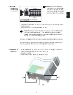
For inserting the system upgrade slot-in boards proceed as follows:

Warning!

 Hazard due to supply voltage and DC-voltage from the

solar modules. Only licensed electricity installers are authorized to
open the connection area and only on condition that is not under
voltage.

Insert slot-in
boards, FRO-
NIUS IG (In-
stallation for
indoor hou-
sing)

insert ENS card only
in this slot

(1)

(2)
(3)
(4)

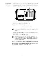
Insert slot-in
boards, FRO-
NIUS IG (In-
stallation for
indoor hou-
sing)

(continued)

- open connection area - see chapter „Open the Housing“
- slide display towards the left side (1) and remove it from the front (2)
- loosen fastening screw and remove board slot cover

Note!

 In dealing with slot-in boards please observe the general

ESD regulations.

- insert board (3) in any one of the slots
- tighten board (3) with fastening screw (4)

For versions for countries where the ENS card is a standard requirement,
the unit will not operate without this card. Legal regulations require a
safety system which does not allow operation of the FRONIUS IG without
installation of ENS.
- power supply feeding operation can be resumed as soon as the ENS

card is placed back in the slot (slot on the left outside, see illustration)

Summary of Contents for IG 15

Page 1: ...FRONIUS IG 15 20 30 40 60 60 HV Grid connected inverters for photovoltaic systems Operating Instructions EN Battery Charging Systems Welding Technology Solar Electronics 42 0410 0828 010 29062016 ...

Page 2: ......

Page 3: ...t features of your new Fronius product This really is the best way to get the most out of all the advantages that your machine has to offer Please also take special note of the safety rules and observe them In this way you will help to ensure more safety at your product location And of course if you treat your product carefully this definitely helps to prolong its enduring quality and reliability ...

Page 4: ......

Page 5: ...All the safety instructions and warning signs on the machine itself must be kept in a legible condition must not be damaged must not be removed must not be covered pasted or painted over General Remarks Important DANGER indicates an imminently hazardous situation which if not avoided will result in death or serious injury This signal word must be limited to the most extreme situations This signal ...

Page 6: ...e of the machine outside the stipulated range is deemed not in accordance with the intended use The manufacturer shall not be liable for any damage resulting therefrom Please refer to the technical data in your instruction manual for accurate information about the permissible ambient conditions Ambient Conditions Qualified Staff The servicing information provided in this instruction manual is only...

Page 7: ...on class B satisfy the emissions criteria for residential and industrial areas This also applies to residential areas in which power is supplied from the public low voltage grid EMC device classification as per the rating plate or technical specifications EMC measures In certain cases even though a device complies with the standard limit values for emissions it may affect the application area for ...

Page 8: ...ment and its implementation as national law electrical equipment that has reached the end of its life must be collected separately and returned to an approved recycling facility Any device that you no longer require must be returned to our agent or find out about the approved collection and recycling facilities in your area Ignoring this European Directive may have potentially adverse affects on t...

Page 9: ...aic System 9 General information 9 Transforming DC into AC electricity 9 Fully automatic operation management 9 Voltage transformation and galvanic insulation 9 Monitoring the mains network 10 Display function and data communication 10 Your advantage 11 Product description 12 The FRONIUS IG Unit 12 How it functions 12 Startup phase 12 Overview for FRONIUS IG for indoor housing 14 Overview for FRON...

Page 10: ...sing 46 Choosing the location outdoor housing 47 Fixing the wall mounting frame for indoor housing 48 Fixing the wall mounting frame for FRONIUS IG Outdoors 49 Connection 52 Connection to the Solar Modules and to the Public Mains 52 Solar modules 52 Mains network monitoring 52 Schemes with more than one inverter 52 AC side overcurrent protection 53 Connection alternatives 53 1 Terminal block 53 2 ...

Page 11: ...ets 65 Class 1 66 Class 2 67 Class 3 68 Class 4 69 Class 5 71 Customer service 72 Annex 73 Technical Data 73 Fronius IG 15 20 30 73 Fronius IG 40 60 60 HV 74 Our product complies with the following standards and regulations 75 Warranty and Liability 76 Fronius manufacturer s warranty 76 Maintenance and disposal of obsolete equipment 76 Maintenance 76 Recycling 76 EC Declaration of conformity 77 ...

Page 12: ...he ENS option is compulsory in only a few countries and only for them the FRONIUS IG unit is available with this option In any case however will the monitoring and safety systems integrated in the FRONIUS IG unit be available as standard equipment Only qualified installers are authorized to open the connection area Opening the connection area is only permitted when it is not under voltage The sepa...

Page 13: ...n remains unchanged At an outside temperature of 10 degrees centigrade the no load voltage of the solar modules must in no case exceed 500 V or 530 V for the IG 60 HV The data sheet of the solar module will tell you the temperature factors applicable for ascertaining the theoretical no load voltage at 10 degrees centigrade In case the solar modules exceed a no load voltage of 500 V or 530 V for th...

Page 14: ...a ny issued by the Association of German Electric Utility Supply Compa nies VDEW Technical Guidelines for parallel operation of self owned photovoltaic generating systems with the low voltage mains network of the utility supply company issued by the Association of Electric Utility Supply Companies of Austria Safety requirements for photovoltaic energy generation plants ÖNORM ÖVE E2750 to the exten...

Page 15: ... in the outside electron shell of a silicon atom arranged around its atomic nucleus they are the so called peripheral valency electrons The sunlight s photons enter the solar cells and concentrate energy in the valency electrons The electron eventually separates from the silicon atom and leaves behind it an atom with a positive charge So that the free electrons will flow in one direction and thus ...

Page 16: ... and the modular electric power will increase while the voltage will remain unchanged The total of all solar modules connected parallel and in series is called solar genera tor mod 1 mod 2 mod n string 1 string 2 string 3 Your roof is your power generator continued tension module 1 Power output and voltage are increased by combining a number of solar cells If solar modules are connected in series ...

Page 17: ...here is a sufficient level of insolation your solar inverter starts supplying and feeding power A few Watts of solar power output are sufficient to achieve this depending on which version the unit is The operation of the FRONIUS IG unit ensures that at any time the maxi mum possible power output is drawn from the solar modules This function is called MPPT Maximum Power Point Tracking It opera tes ...

Page 18: ...e mains network This responsibility comprises all measures necessary for the protection of persons and machines in case of a power blackout The FRONIUS IG unit is programmed to stop operation immediately and stop supplying power whenever conditions in the mains network deviate from standard for example when power is switched off or in case of any other kind of interruption There are several ways h...

Page 19: ...G unit complies with a whole number of requi rements established for the safety of people and other household ap pliances as well for its own safety Some of these requirements are ability to monitor the mains network the quality of the electricity supplied detection of outside disturbance and interference for example mobile telephones Annexed you will find the respective certificates Your advan ta...

Page 20: ...es at any time MPP tracking As soon as dusk begins there is no more sufficient energy available to feed into the mains network the FRONIUS IG unit fully shuts off the mains connection during the night the FRONIUS IG unit does not draw any energy from the public mains the data and parameters set remain available it is also possible to shut the unit off manually How it func tions After having switch...

Page 21: ... ENS will be tested and synchronized the screen displays SYNCENS Depending on the operating status of the ENS test and synchronization may take up to several seconds 6 Operation of feeding power supply into the mains network After termination of the tests the FRONIUS IG unit starts feeding power into the mains network The LED lights up green and the FRONIUS IG unit starts operating Whenever two sc...

Page 22: ... display 5 keyboard 6 slot in board area 7 various versions of connection plate 8 connection area to be opened only by licensed electricity installers 9 power stage separately insulation encased to be opened only by Fronius trained service staff Overview for FRONIUS IG for indoor housing 9 2 6 7 5 4 3 8 1 ...

Page 23: ...utside 6 covering for AC connection and slot in board area 7 connection rail Multicontact 8 cover slide to protect the buttons and the display from the sun s rays Note We recommend that the cover slide is pushed in front of the display in cases of direct sunshine Overview for FRONIUS IG Outdoors 7 1 1 2 1 6 3 4 5 2 8 ...

Page 24: ...e function of the FRONIUS IG However for safety reasons we recommend that the insulation fault is remedied as soon as possible Depending on the country setup the inverter can also disconnect from the public grid when there is an insulation error and stop feeding energy into the grid The FRONIUS IG with display shows a status message A message is displayed in the FRONIUS IG access software for the ...

Page 25: ...ation can be resumed manually at any time see chapter Setup Menu 5 LED lights up red general status the respective service code is displayed on the screen Inverter does not feed energy into the public grid A list of all service codes the corresponding status informations their status causes and repair measures can be found in the chapter Sta tus Diagnosis and Repair of the installation and service...

Page 26: ...ny adjustments in order to be able to get it to operate fully automatic and feed power into the mains The display is powered by the solar module and is therefore available throughout the day Important The display of the FRONIUS IG is not a calibrated measuring device A slight deviation by a few percent is inherent in the system Therefore a calibrated meter is required for accurate settlement of da...

Page 27: ...ter 6 appears with data readings which are directly related to the public mains network 7 appears with data readings which are directly related to the solar modules 8 appears with data readings which are related directly to the FRONIUS IG unit 9 appears with data readings which are related to environment conditions like insolation and temperature optional 10 appears with data readings which are tr...

Page 28: ...em Year a real time clock is required The menu item Year is only supported when the option data recor der is connected This system upgrade is equipped with a real time clock 1 2 3 4 A B D A B From the menu level you enter the display mode or the setup menu Move into the menu surface by pressing key C Menu level C C the screen displays Menu the display is operating in the menu level ...

Page 29: ...t day display mode Year shows data for supply into the mains in current calendar year only in combination with data recorder option display mode Total shows data for supply into the mains since your FRONIUS IG unit has been first operating Scrolling between dis play functions A B A B select the desired display mode see above scroll between the display functions available with keys A or B A B ...

Page 30: ...mum V module temperature minimum C alternat also F output reading of consumption meter W ambient temperature C alternnatively also in F insolation W m insolation maximum W m ambienttemperature maximum C alternat also F ambient temperature minimum C alternat also F time HH MM Scheme of display rea dings The following scheme contains a brief list of the display readings available Display readings wi...

Page 31: ... FRONIUS IG unit will interrupt power supply for safety reasons power supplied power supplied to mains at the parti cular moment Ampere power supplied power supplied to mains at this mo ment Watt for the next item press key B to scroll back press key A mains frequency cycles mains voltage Volt A B Display mode Now Displays present readings select display mode Now chapter The Display the first disp...

Page 32: ... by an insufficiently insulated DC cable or by defective solar modules In case of an insufficient isolation resistance you must in any case contact your Fronius service partner Important Only an isolation resistance of less than 500 kOhm indicates that there is an error Whenever a higher insulation reistance is shown it is not to be interpreted as an error Whenever there is an isolation resistance...

Page 33: ...an also be set for F in setup menu temperature sensor Nr 2 sensor card optional Display mode Now continued insolation insolation power output impact per square meter Watt m sensor card option Display example for positive poten tial sign Short circuit between DC line and earth Display example for negative po tential sign Short circuit between DC line and earth ...

Page 34: ...ly kWh operating hours for FRONIUS IG unit The information given above does not apply for the data recorder option If the data recorder option is available the display values listed always apply for the whole of the mains supply feed day Display mode Year shows readings of power supply for the current calendar year only in conjunction with data recorder Display mode Total shows readings of power s...

Page 35: ... during period monito red kWh MWh Due to different monitoring systems there can be deviations in compari son with readings of other metering instruments For invoicing of the energy supplied only the readings of the calibrated meter supplied by the electric utility company are relevant press key B for next item to scroll back press key A Display mode Day Year Total continued Indication of CO2 emiss...

Page 36: ...Energy consumption meter reading energy consumed during ob servation period kWh MWh applicable for consumption sensor Display mode Day Year Total continued maximum ambient tempera ture highest temperature reading during observation period C can also be set for F in setup menu temperature sensor No 2 applicable for sensor card minimum ambient tempera ture lowest temperature reading at solar modules...

Page 37: ...lthough the FRONIUS IG unit is not operating during the night all data required for the sensor card option are monitored and saved around the clock The following brief scheme shows the menu items provided for readju sting preset parameters of the FRONIUS IG unit The Setup Menu List of menu items Standby Contrast LightMode currency Enter 0 7 AUTO ON Cash OFF rate kWh 01 99 100 FRONIUS IG 00 IG NR D...

Page 38: ...ossible way D Enter the setup menu move to to the menu level chap ter Navigating in the Display select mode Setup 5 with keys A or B enter the mode Setup 5 press key Enter D 1 2 3 4 5 A B D A B Standby the first item on the menu is displayed Scroll among menu items A B A B select the desired display mode see above scroll with keys A or B among the menu items available A B ...

Page 39: ...creen STANDBY ENTER The orange flashing LED stops with dusk arriving After the subsequent sunrise the power supply operation into the mains is resumed automatically after termination of the startup phase the LED is illuminated green mains supply operation can be resumed at any time whenever the LED is flashing orange deactivate standby LED with green light activate standby manual shutoff of operat...

Page 40: ... D As contrast depends on tempera ture it may be necessary to adjust the menu item Contrast when ambient conditions change Settings for minimum possible contrast 0 upto maximum possib le contrast 7 accept press key Enter D maintain previous setting press key Esc C select from settings 0 to 7 press key A or B C D C ...

Page 41: ...ination It is not necessary to deactivate the display itself because its energy consumption is less than one mW 1 1000 W 2 1 The display illumination will stop 30 seconds after the last time a key has been pressed accept press key Enter D maintain previous setting press key Esc C 2 The display will remain perma nently illuminated for the duration of the operation of power supply into the mains acc...

Page 42: ...shing select a character for the first digit by pressing key A or B confirm by pressing key Enter D next digit starts flashing 1 follow same procedure as descri bed above for subsequent digits accept the currency selected by pressing key Enter D to maintain previous setting press key Esc C A B D A C D decimal point starts flashing move the decimal point to the position desired by pressing keys A o...

Page 43: ...follow procedure as described above for first digit accept the IG No selected press key Enter D maintain previous setting press key Esc C Note Allocate an own address to each FRONIUS IG when con necting several FRONIUS IG into a data communication network using data recorders It is important to give each FRONIUS IG an own address so that the data recorder can differentiate between the individual s...

Page 44: ...the data link is not functioning correctly B A B A Signal Card active The Signal Card s acoustic signal sounds for confirmation Important Check the signal lines if the signal fails to sound Signal Card not installed D C C B Start the Signal Card test by pressing the Enter key D D Press key B to call up the Sig nal Card test ...

Page 45: ... follow the same procedure as described above for subsequent digits accept the date selected by pressing key Enter D to maintain previous setting press key Esc C C D D B A B D A D C C D D 2 Enter time e g 15 47 first digit starts flashing select a figure for the first digit by pressing key A or B confirm by pressing key Enter D next digit starts flashing for subsequent digits follow same procedure...

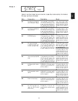
Page 46: ...r D Isolation warning menu display Press Enter D Use button A or B to selected the Off or On setting Press Enter D to apply the setting When the setting is Off the State 502 Isolation warning is deactiva ted Off is recommended for solar modules with a high ohm grounded DC and DC connection ...

Page 47: ... alternately Escape Press Esc key C twice C 2x D D STATE_PS Status display of power stage sets Press Enter key D In this case for example the first power stage set PS00 is on Standby Standby means no electricity is being fed into the public mains Press Enter key D D D Alternately Display of the most recently stored service code e g State 406 Important The most recently stored service code and the ...

Page 48: ...o display type number of ENS press key Enter D exit with key Esc C to switch into display of version number for ENS press keys A or B exit with key Esc C Note in case the FRONIUS IG unit is not equipped with the ENS option type num ber and version number cannot be displayed after the Enter key D has been pressed the message N A is displayed on the screen exit by pressing key Esc C C D display type...

Page 49: ...ed flexibility all upgradings are also available in a version with external housing Additional information The FRONIUS IG unit is prepared for a whole series of system upgrades such as for communicating between FRONIUS IG and outside system extensi ons for example with other FRONIUS IG units Data logger for recording and managing data from your photovoltaic system by PC including datalogger and mo...

Page 50: ...mple no adequate heat transfer away from the control panels the power will be derated for auto protection of the FRONIUS IG unit derating the power reduces the output of the FRONIUS IG unit for a short period sufficient to ensure that the temperature will not exceed the admissible parameter your FRONIUS IG unit will remain ready for operation as long as possible without any interruption Even if th...

Page 51: ...43 EN EN Installation manual ...

Page 52: ...ed power stage on condition that it is not under voltage Opening connection area FRONIUS IG installation of the indoor housing insert screwdriver into the borehole 1 at the bottom of the FRONIUS IG unlock cover 2 of connection area by lifting the screwdriver carefully at the end of its handle pull cover 2 of connection area downwards and away Important To close the connection area put on cover 2 a...

Page 53: ...from the solar modules Only Fronius trained service staff are authorized to open the separately insulation enclosed power stage 3 4 5 loosen four screws 1 remove cover 2 loosen securing screw 5 and remove wall mounting frame FRONIUS IG Outdoors FRONIUS IG installation of the indoor housing continued 2 1 1 ...

Page 54: ...nts e g from farm animals horses cattle sheep pigs etc stables or adjoining areas storage areas for hay straw chaff animal feed fertilizers etc Choosing the location indoor hou sing Installation Make the best possible use of your FRONUS IG unit by additionally ob serving the following conditions mains impedance should not be unnecessarily increased by a too nar row AC conductor cable cross section...

Page 55: ...y pro tected fitting position for the FRONIUS IG Outdoors with exterior casing e g in the area of the solar module or under a projecting roof FRONIUS IG can be installed vertically as well as horizontally accor ding to chapter Fixing the wall mounting for FRONIUS IG Outdoors For use in environments with heavy dust development If necessary remove the fan plates and clean the integrated fly screen D...

Page 56: ... AC and DC cable as described in chapter Connection close connection area and mount cover by means of tightening screw The housing is designed for a cable channel of up to 50 mm height which can be located directly below the connection area without cables visible below the FRONIUS IG unit impairing access to the connection area and the slot in board area Fixing the wall mounting frame for indoor h...

Page 57: ...eeped in water Vertical mounting position remove draining screw 1 Horizontal mounting position remove draining screw 2 26 mm Important Should a cable channel be located below the FRONIUS IG unit the following must be obser ved lower edge of FRONIUS IG unit will be located exactly 26 mm beneath the wall mounting frame Fixing the wall mounting frame for indoor hou sing continued vertical mounting po...

Page 58: ...ng illustration shows both parts 1 and 2 of the wall bracket Both parts are included with the FRONIUS IG The illustration shows how the FRONIUS IG is hung in part 1 Part 2 is fitted as follows Slacken the screws 3 on the bottom of the FRONIUS IG Fit part 2 using the screws 3 2 1 3 ...

Page 59: ... 2 of the wall bracket Hang the FRONIUS IG into part 1 of the wall bracket and secure using part 2 of the wall bracket Fit part 2 of the wall bracket using suitable screws and rawl plugs Fit AC and DC cables as described in the section Connection 26 mm Important Pay attention to the following if a cable duct is fitted underneath the FRONIUS IG The bottom edge of the FRONI US IG is exactly 26 mm un...

Page 60: ...n order to secure a symmetric feed in of the power supply the FRONIUS IG units should be connected evenly to all 3 phases If you have any doubt you should approach your specialized dealer whe never there are technical problems Schemes with more than one inverter Connection to the Solar Modules and to the Public Mains The following points are important for the most economic use of the FRO NIUS IG u...

Page 61: ...ctions for AC and DC connection cables cable without wire end ferrules 6 mm and 10 mm cable with wire end ferrules 6 mm Note Tighten the screws of the terminal strip with 1 8 Nm 1 Terminal block AC side over current pro tection Important We recommend the following for AC side overcurrent protec tion A separate 16 A fuse for each Fronius IG 15 and 30 A separate 25 A fuse for each Fronius IG 40 and ...

Page 62: ...e AC connection cable lead the connection cable for the DC supply through the connector rail and strain relief device and slide it into the terminal block connect the leads of the connec tion cable according to terminal markings fix the connection cables with the strain relief device close connection area termnal rail for the leads of the DC connection cable PE N L1 DC DC AC feed the 3 pole connec...

Page 63: ...n of the FRONIUS IG unit Before dis connecting the strings always first disconnect the mains supply or switch the FRONIUS IG to standby operation Not complying with this instruction may damage the connection plugs Should an electric arc develop during disconnecting both plug and socket must be replaced Do not re use defective DC plugs To make installation and maintenance work easier the solar modu...

Page 64: ...eter Connection earth yellow green Connect phase brown Connect zero lead blue Install the AC plug as follows slide parts 2 and 3 on to the mains cable as shown in the illustration below connect the mains cable leads with the AC plug as shown in opposite illustration Bare the mains cable as shown in the illustration for the AC plug type connector 20 mm 5 mm 3 AC plug connection and DC plug continue...

Page 65: ...ld an electric arc develop during unplugging both plug and socket must be replaced Never re use damaged DC connections Note When installing DC connections for solar modu les make sure that the plus and minus poles correspond with the respective symbols DC plugs Connector rail with 5 pairs of DC plugs DC sockets AC plug Illustration also applicable for connector rail with 1 5 DC plug pairs fix the ...

Page 66: ...ouse distributor panel Failing to comply with this instruction may damage the plug connections Should an electric arc develop during unplugging both plug and socket must be replaced Never re use damaged DC plugs lead the 3 pole connection cable to the public mains through connector rail 3 and strain relief device and slide it into the terminal block 4 connect the leads of the connection cable as m...

Page 67: ...partners connected system upgrading please con sult the chapter LocalNet as soon as the photovoltaic modules produce sufficient power the LED lights up orange and the screen starts displaying the startup procedure the orange light of the LED indicates that the automatic startup procedu re of the FRONIUS IG unit will begin shortly after the FRONIUS IG unit has started automatically the LED light tu...

Page 68: ...is pre set for quite a number of system upgrades data recorder for recording and managing the data of your photovoltaic system on your personal computer including modem tie in wie z B data recorder for recording and managing photovoltaic system data on your PC including data recorder and modem connection Various large displays FRONIUS IG Public Display Actuators Relays Alarm FRONIUS IG Signal Card...

Page 69: ...area see chapter Open the Housing slide display towards the left side 1 and remove it from the front 2 loosen fastening screw and remove board slot cover Note In dealing with slot in boards please observe the general ESD regulations insert board 3 in any one of the slots tighten board 3 with fastening screw 4 For versions for countries where the ENS card is a standard requirement the unit will not...

Page 70: ...l system upgradings the respecti ve units must have an individual number To define each FRONIUS IG clearly in the LocalNet an individual number must also be allocated to each FRONIUS IG For the respective procedure please consult the chapter Setup Menu in your operating instructions Configuration Insert slot in boards FRO NIUS IG for external mounting Release four screws 1 Remove cover 2 Release f...

Page 71: ... Card COM Card 5 Blind plug 6 Data cable Sensor Box in external Housing IN OUT IN OUT PC IN OUT ENS ENS ENS RS 232 Note Basically the order of sequence for placing the cards does not matter Important however is One FRONIUS IG can have only one COM card One network can contain only one data recorder More information on the various system upgrade possbilities you will find in the respective service ...

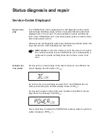
Page 72: ...RONIUS IG unit in the photovoltaic system as well as instal lation and operation errors Whenever the self diagnostic system has identified a particular defect the respective service code is displayed on the screen Note Display of a service code for a short time may be a result of the control procedure of your FRONIUS IG unit If subsequently it continues to operate normally there has not been a cas...

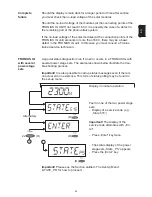
Page 73: ...lete failure Display in normal operation D Fault in one of the two power stage sets Display of a service code e g State 515 Alternately D Important The display of the service code alternates with En ter Press Enter key twice D 2x FRONIUS IG with several power stage sets A special status diagnostic is run if an error occurs in a FRONIUS IG with several power stage sets The examples shown below illu...

Page 74: ...he service code fails to disappear As soon as the mains volta ge after detailed check pro cedure has returned to ad missible range FRONIUS IG resumes feeding power into the mains network 101 Mains voltage not wi thin admissible range Check mains voltage If the service code does not disappear you should contact your installation specialist As soon as mains frequen cy after detailed check pro cedure...

Page 75: ...k has returned to the admissible range your FRONIUS IG resumes fee ding power into the mains network 203 Excessive mains frequency Check mains frequency If the service code does not disappear you should contact your installation specialist As soon as the mains fre quency after a detailed check has returned to the admissible range your FRONIUS IG resumes fee ding power into the mains network 204 In...

Page 76: ...u should contact your in stallation specialist Short interruption of power supply feeding into mains network caused by tempe rature excursion air vents clogged 303 temperature excursion AC side after a two minutes coo ling phase your FRONI US IG unit begins star ting up again clean air vents Should the service load appear permanently you should contact your in stallation specialist Short interrupt...

Page 77: ...404 No communication possible between the control unit and ENS FRONIUS IG has no net work connection Check if the mains supply isola tor is switched on If Service Code is dis played permanently you should contact a Fronius trained service technici an If it is possible your FRONI US IG unit will resume the power feeding operation af ter successfully completing another attempt to connect 405 Incorre...

Page 78: ...nently contact a Fronius trained service technician Code Designation Description Repair Orange LED lights up then the FRONIUS IG attempts a new start 416 Communication with IG Ctrl not possible If Service Code is dis played permanently contact a Fronius trained service technician 443 Orange LED lights up and then the FRONIUS IG attempts a restart Energy transfer not possible If the service code co...

Page 79: ...1 EEPROM faulty If necessary reconfigu re metering channels If Service Code is dis played permanently contact a Fronius trained service technician Too many power supplies recognised in the system 512 Too many power sup plies in the system In spite of insufficient power generation the temperature in the unit is too high 501 defective ventilator air vents blocked Class 5 service codes generally do n...

Page 80: ...ssage pre sent for one of the po wer stage sets Carry out analysis Sec tion entitled The Set Up Menu State_PS for further details Contact Fronius trained service technician if service code is displayed permanent ly Important contact your Fronius dealer or Fronius trained service partner if an error not mentioned in the schedule appears frequently or perma nently Customer service Code Designation D...

Page 81: ... during night 0 15 W Consumption during operation 7 W Cooling controlled forced ventilation Protection type indoor outdoor housing IP 21 IP 45 Size l x w x h 366 x 344 x 220 mm 500 x 435 x 225 mm Weight 9 kg max 13 kg Admissible ambient temperature at 95 rel humidity 20 50 C Protection devices IG 15 IG 20 IG 30 DC isolation monitoring Warning Shut off when RISO 500 kilohms DC excess voltage protec...

Page 82: ...0 15 W Consumption during operation 12 W Cooling controlled forced ventilation Protection type indoor outdoor housing IP 21 IP 45 Size l x w x h 610 x 344 x 220 mm 733 x 435 x 225 mm Weight 16 kg max 22 kg Admissible ambient temperature at 95 rel humidity 20 50 C Protection devices IG 40 IG 60 IG 60 HV DC isolation monitoring Warning Shut off when RISO 500 kilohms DC excess voltage protection inte...

Page 83: ...ropout caused either by shutoff effected by the utility supplier or by power transmission line failure the power supply feeding will be immediately interrupted In particular the following standards and regulations are being complied with EN 61000 3 2 harmonic oscillations EN 61000 6 2 EN 61000 6 3 EN 6100 6 3 EMV interference emissions EN 6100 6 2 EMV interference immunity EN 50178 electric safety...

Page 84: ...e register at www solarweb com Fronius manufacturer s warranty Warranty and Liability Should your inverter be replaced at some future date Fronius will accept the obsolete equipment back and provide for its proper recycling Maintenance and disposal of obsolete equipment Recycling The filter should be checked regularly to maintain its high quality and to ensure that it is functioning correctly Main...

Page 85: ...77 EN EN ...

Page 86: ...78 ...

Page 87: ...79 EN EN ...

Page 88: ...80 ...

Page 89: ...81 EN EN ...

Page 90: ...82 ...

Page 91: ......

Page 92: ... com http www fronius com USA A Fronius Worldwide www fronius com addresses Fronius USA LLC Solar Electronics Division 6797 Fronius Drive Portage IN 46368 E Mail pv us fronius com http www fronius usa com Under http www fronius com addresses you will find all addresses of our sales branches and partner firms ...

Reviews: