


13
EN
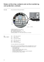
Possible relay
contact functions
(2)
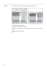
Transformer con-
nections IN1 / IN2
The temperature of the external medium-voltage transformer can be monitored and eval-
uated via the IN1 and IN2 connections. The inverter then adjusts the power of feeding in
according to the temperature of the medium-voltage transformer.
If a specific temperature is exceeded, the
inverter reduces the power of feeding in
and a warning message is shown on the
display.
The grid power feed operation is not inter-
rupted.
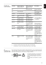
Function
Switch contact ac-
tivation criterion
1)
Switch contact de-
activation criteri-
on
2)
Description
Off
-
Permanently OFF
Function switched
off
On
Permanently ON
-
Test function for NO/
alarm contact
AC Open
AC contactor is open
AC contactor is
closed
No contactor error
signal or AC grid
Fan On
Cabinet fan in opera-
tion
Cabinet fan not
working
External ventilation /
air conditioning can
be activated
> 40 °C
max. internal tem-
perature >/= 40 °C
max. internal tem-
perature </= 30 °C
> 50 °C
max. internal tem-
perature >/= 50 °C
max. internal tem-
perature </= 40 °C
Sig. Rel.
NO/alarm contact
trips
Error confirmation at
the touch of a button
/ by Solar Net com-
mand
Status indicator / re-
lay contact switches
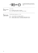
Running
Inverter feeding en-
ergy into the grid
Inverter not feeding
energy into the grid
Control of powered
non-return valve
Warning
Defined warning sta-
tus codes
Error confirmation at
the touch of a button
/ by Solar Net com-
mand
NO/alarm contact
activation, when cer-
tain warning status
codes occur at a
specific frequency
according to the 'Er-
ror-Counter' Service
menu
Error
Defined error status
codes
Error confirmation at
the touch of a button
/ by Solar Net com-
mand
NO/alarm contact
activation, when cer-
tain error status
codes occur at a
specific frequency
according to the 'Er-
ror-Counter' Service
menu
1)
Activation = the NC for the relay contact opens, the NO closes
2)
Deactivation = the NC for the relay contact closes, the NO opens
Warning
IN1