Froling S3 Turbo 30 Owner'S Manual Download Page 18

CAUTION

ADJUSTMENT OF THE FLUE DRAFT HIGHER THAN 0.12 INCHES WATER COL‐
UMN (30 Pa) COULD CAUSE A FIRE TO BURN OUT OF CONTROL AND AN UN‐
SAFE CONDITION!

❒ Maximum permitted setting: 0.12 inches WC (30 Pa)

Ideal setting: 0.04 inches WC (10 Pa)


2.4 Safety markers

WARNING

Danger if signage is illegible!

❒ Ensure that all safety, warning and operating instructions are always in a clearly

legible condition.

❒ Replace damaged stickers and signs immediately.

➥ Over time stickers and signs can get dirty or otherwise unrecognizable which

means that dangers cannot be identified and the necessary operating informa‐

tion cannot be observed. This poses a risk of injury.


The following stickers are located in the work area. They refer to the area immediately
surrounding where they are affixed.

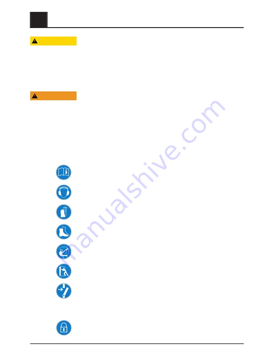
2.4.1 Mandatory signs

Refer to the operating instructions
Only use the indicated system once you have read the operating instructions.

Wear hearing protection
This sign indicates that hearing protection must be worn in the area concerned.

Wear protective gloves
This sign indicates that protective gloves must be worn in the area concerned.

Wear safety shoes
This sign indicates that safety shoes must be worn in the area concerned.

Wear a dust mask
This sign indicates that a dust mask must be worn in the area concerned.

Keep the doors closed
Keep the doors closed during operation.

Turning off the main switch
Switch off the main switch and take precautions to prevent accidental switching on be‐
fore carrying out work to the system
Switch off the main switch for the fuel infeed and take precautions to prevent acciden‐
tal switching on before entering the fuel storage room.

Securing the main switch
Switch off the main switch and secure with a padlock when carrying out maintenance
work to the boiler.


2

Safety

Safety markers

18

Froling GesmbH | A-4710 Grieskirchen, Industriestraße 12 | www.froeling.com

Summary of Contents for S3 Turbo 30

Page 1: ...b H Industriestra e 12 A 4710 Grieskirchen Tel 43 0 7248 606 0 Fax 43 0 7248 606 600 info froeling com www froeling com 4 Owner s Manual S3 Turbo Read and follow the operating instructions and safety...

Page 2: ...mney connection 17 Basic data for designing the chimney connection 17 2 4 Safety markers 18 2 4 1 Mandatory signs 18 2 4 2 Prohibitions 19 2 4 3 Warning signs 19 2 4 4 Signage on the boiler 20 Notice...

Page 3: ...thermal storage or if the thermal storage is too small 48 5 4 Heating up the boiler 49 5 5 Add more firewood during the operation 53 5 6 Remove ash 55 6 Maintaining the boiler 57 6 1 Safety instructi...

Page 4: ...ble 73 7 2 1 Reset the high limit thermostat 74 7 3 After troubleshooting 74 8 Dismantling and disposal 75 9 Technology 76 9 1 Dimensions 76 9 2 Components and connections 77 9 3 Technical data 78 Tab...

Page 5: ...fety regulations apply to the area of application of the system Images in these instructions are intended solely to aid understanding and may differ from the actual design NOTICE SAVE THESE INSTRUCTIO...

Page 6: ...rbo 2 Boiler controller control panel 3 WOS lever 4 Actuator of primary air flap 5 Actuator of secondary air flap 6 Heat exchanger cleaning door 1 Overview Front view 6 Froling GesmbH A 4710 Grieskirc...

Page 7: ...2 Back view 1 Boiler flow connection 2 Induced draft fan 3 Thermal discharge safety device connection 4 Drainage 5 Boiler return connection Overview 1 Back view Owner s Manual S3 Turbo B1390016_en us...

Page 8: ...door 4 Combustion chamber door 5 Fuel loading chamber 6 Combustion chamber 7 Heat exchanger with spiral springs 8 In flue gas nozzle Flue gas temperature sensor and broadband lambda probe 1 Overview C...

Page 9: ...o fire wood boiler is designed and constructed for the highly efficient com bustion of fire wood Do not burn other fuels in the fire wood boiler S3 Turbo The S3 Turbo boiler is a not self contained we...

Page 10: ...signal word indicates important but not safety related information e g damage to property or pollution Safety information in operating instructions Safety information can refer to certain individual o...

Page 11: ...re specified in these operating instructions in both SAE units and SI units The SAE unit appears first followed by the SI unit in brackets Example using information about heat output 17 5 BTU h kW equ...

Page 12: ...water Do not alter the boiler controller DO NOT BURN GARBAGE GASOLINE NAPHTA ENGINE OIL OR OTHER IN APPROPRIATE MATERIALS DO NOT USE CHEMICALS OR FLUIDS TO START THE FIRE DO NOT OPERATE WITH FLUE DRA...

Page 13: ...INSTALLATION AND OPERATION CLEARANCES TO COMBUSTIBLES MUST BE MAINTAINED The diagram below shows how much space is required for the system in the boiler room The boiler may only be installed on non c...

Page 14: ...e used directly in swimming pools or thermae Use a heat consumer of the right size to consume the heat Do not use the heating water as drinking water To ensure good water quality during operation avoi...

Page 15: ...pplicable local regulations Recommended size of air openings according to NFPA 54 and NFPA 211 The boiler requires a fresh air supply of between 1 sq in per 2 500 BTU h and 1 sq in per 4 000 BTU h 550...

Page 16: ...are over filling the boiler with wood and it is cycling on and off rather than having continuous run times Over filling the boiler may result in corrosion of the firebox wall damage to the com bustion...

Page 17: ...nection pipe must have a diameter of at least 6 150 mm The individual pipe sec tions must be joined together with at least three self tapping screws and the joins sealed using high temperature silico...

Page 18: ...the indicated system once you have read the operating instructions Wear hearing protection This sign indicates that hearing protection must be worn in the area concerned Wear protective gloves This si...

Page 19: ...embranes Observe the information on the packaging and containers Danger from carbon monoxide There is a risk of poisoning from a possible concentration of carbon monoxide in the fuel storage room and...

Page 20: ...ons see the plaque located directly on the boiler DANGER Working on electrical components may cause severe injuries from electric shocks WARNING The electrical system of the boiler shall be supplied f...

Page 21: ...RLY TO REMOVE ACCUMULATED CREOSOTE AND ASH ENSURE THAT THE HEAT EXCHANGER FLUE PIPE AND CHIMNEY ARE CLEANED AT THE END OF HEATING SEASON TO MINIMIZE CORROSION DURING THE SUMMER MONTHS THE APPLIANCE FL...

Page 22: ...event of runaway fire Turn off Emergency Switch if installed Do not open any Boiler or Ash pit Door DO NOT SWITCH OFF MAIN ISOLATOR AT CONTROL SYSTEM In case no Emergency Switch is installed 1 Open In...

Page 23: ...longer live and secure so that they remain off for the du ration of the work Follow the five safety rules Disconnect Secure against switching back on Check the system is no longer live Earth and shor...

Page 24: ...ibed intervals Ensure that the chimney vent is cleaned regularly Do not use any hydrogen halides or cleaning agents containing chlorine in the boiler room Observe the safety signs around the system Us...

Page 25: ...generally be worn for work on the boiler Only touch the boiler using the handles provided Insulate the flue gas pipes and do not touch them during operation Keep children and unauthorized persons awa...

Page 26: ...ss in the boiler The combustion of firewood can cause tar oil deposits in the boiler and chim ney Skin contact can be seriously harmful to health Leaking flue gas WARNING Risk of poisoning from flue g...

Page 27: ...matic operation Leave the boiler room and close the access door Ensure that heat is being consumed To do this activate all consumer loads Once the boiler temperature has fallen to 185 F 85 C return th...

Page 28: ...he manufacturers and the suppliers in dealing with the sys tem and its components and can independently detect potential hazards and avoid the associated risks Froling customer service or an authorize...

Page 29: ...g heating flue gas and ventilation systems as well as fuel stores for prop er operation and fire safety Cleaning heating plants smoke ducts and ventilation systems Knowledge of provisions under buildi...

Page 30: ...loves are used to protect the hands against friction abrasion puncture or deeper injuries and contact with hot surfaces Safety shoes Safety shoes protect feet from crushing and falling parts as well a...

Page 31: ...iner Firebricks The combustion chamber must be disposed of as construction waste 2 11 The operator s responsibilities Operator The operator is the person who operates the system for commercial or econ...

Page 32: ...ly fuels approved by the manufacturer are used The operator must ensure that the prescribed safety tests are performed The operator must ensure that the regulatory approval requirements are respect ed...

Page 33: ...w 1 Boiler S3 Turbo 2 Boiler controller control panel 3 WOS lever 4 Actuator of primary air flap 5 Actuator of secondary air flap 6 Heat exchanger cleaning door Description of the boiler 3 Front view...

Page 34: ...connection 2 Induced draft fan 3 Thermal discharge safety device connection 4 Drainage 5 Boiler return connection 3 Description of the boiler Back view 34 Froling GesmbH A 4710 Grieskirchen Industrie...

Page 35: ...hamber door 4 Combustion chamber door 5 Fuel loading chamber 6 Combustion chamber 7 Heat exchanger with spiral springs 8 In flue gas nozzle Flue gas temperature sensor and broadband lambda probe Descr...

Page 36: ...box is loaded with kindling cardboard start up fuel and firewood place several sheets of crumpled newspaper inside the lighting door With the fuel loading door and the lighting door open turn on the b...

Page 37: ...ection Agency Because the S3 Turbo is a batch fed boiler and is intended to burn at maximum output whenever it is operating daily operating efficiency and An nual Fuel Utilization Efficiency are the s...

Page 38: ...te length and split into pieces 4 5 10 12 cm thick The best length is 21 52 cm for the S3 Turbo boiler The wood is best stored in the open air under cover Wood will dry most quickly if it is carefully...

Page 39: ...llowing precautions Initial startup should be carried out with an authorized installer or with Froling cus tomer services The customer is responsible for ensuring the following prior to initial start...

Page 40: ...or defects at least once a day Before starting work make sure that all covers and safety devices are installed and work properly Never disable or bypass safety equipment during operation Do not alter...

Page 41: ...ort reduces value Long reduces value in increments of 10 Long 10 secs reduces value in increments of 100 Enter key Navigation go to selected menu Parameter change Releases the parameter for editing or...

Page 42: ...11 Shows that the heating circuit pump of the second heating cir cuit is active 12 Shows that the heating circuit pump of the first heating circuit is active At the service technician user level the...

Page 43: ...tions of the boiler and or the Instructions for the procedure for measuring emissions for the firewood boiler long Function not used Info key Keystroke Function Short Heating 08 02 BASIC DISPLAY Menu...

Page 44: ...eating cir cuit controller is deactivated Party program key Keystroke Function shor t Heating 08 02 PARTY MODE is not possible in boiler display To activate party mode on the room console Caution Func...

Page 45: ...formation in the operating instructions of the room console long Heating 08 02 CONTINUOUS setback MODE is not possible in boiler display To activate continuous setback mode on the room console Caution...

Page 46: ...charge status without on off cycling of the boiler 100 charge status means an aver age thermal storage temperature of boiler setpoint temperature standard 185 F 85 C minus a certain temperature which...

Page 47: ...n tent See Fuel table page 48 Right amount of fuel The following tables give you an idea of the required amount to heat the thermal stor age The calculation of the tables below is based on the formula...

Page 48: ...0 3 3 Soft wood approx 53 lbs 24 kg approx 86 lbs 39 kg Hardwood approx 88 lbs 40 kg approx 143 lbs 65 kg 2 3 Soft wood approx 35 lbs 16kg approx 57 lbs 26 kg Hardwood approx 60 lbs 27 kg approx 95 lb...

Page 49: ...x 88 lbs 40 kg approx 143 lbs 65 kg 2 3 Soft wood approx 35 lbs 16 kg approx 57 lbs 26 kg Hardwood approx 60 lbs 27 kg approx 95 lbs 43 kg 1 3 Soft wood approx 18 lbs 8 kg approx 29 lbs 13 kg Hardwood...

Page 50: ...rox 1 2 3cm After the first layer of wood lay cardboard across the whole area Add start up fuel so that the amount is approximately 10 of the weight of the ex pected firewood load in other words if yo...

Page 51: ...l sheets of crumpled newspaper inside the lighting door Briefly press the DOWN arrow on the navigation keys The induced draft fan switches off Ignite paper with a lighter at several positions Press th...

Page 52: ...f 130 C 266 F close the pre heating chamber door and insulated door NOTICE Remain with the boiler during the entire lighting process 5 Heating the boiler Heating up the boiler 52 Froling GesmbH A 4710...

Page 53: ...flue gas generation Open the fuel loading door slowly and carefully Close the fuel loading door immediately after checking or adding more firewood Open the insulated door und observe the boiler s bas...

Page 54: ...antity actually needed to load the thermal storage The fuel quantity actually required is determined by the difference of the fuel quantity shown on the display and the current remaining fuel in the f...

Page 55: ...prons It is recommended that you do not remove the ash in the combustion chamber during each heating up process but rather only when the middle row of holes in the combustion chamber guards is no long...

Page 56: ...passage to the left and right of the combustion chamber with small brush and remove ash Shovel the ash into the container provided Fire proof container with cover Close all boiler doors again after r...

Page 57: ...rs and safety devices are installed and work properly THE HEAT EXCHANGER DRAFT INDUCES FLUE PIPE AND CHIMNEY MUST BE CLEANED REGULARLY TO REMOVE ACCUMULATED CREOSOTE AND ASH ENSURE THAT THE HEAT EXCHA...

Page 58: ...at safety equipment is func tioning properly Operator Remove ash and clean the grating Operator twice a month during the heating period Remove soot tar oil and ash deposits from the chimney connection...

Page 59: ...ecifications If the system pressure decreases Add water NOTICE If this happens frequently the seal of the heating system is faulty Inform your installer If large pressure fluctuations are observed Ask...

Page 60: ...he ash from the fuel loading chamber into the combustion chamber using the furnace tool Open the combustion chamber door and remove ash with a round ash shovel Fire proof container with cover 6 Mainta...

Page 61: ...ombustion chamber with small brush and remove ash Shovel the ash into a container Fire proof container with cover Open the heat exchanger cleaning door and remove the ash with the furnance tool Fire p...

Page 62: ...crape the ribs with a screwdriver Check the secondary air inlets and clean with an ash vacuum if necessary Place the two halves of the grating back on the combustion chamber Ensure that they are posit...

Page 63: ...1 20 mm of the sensor re mains protruding from the bushing and secure with fixing screw Put the thermal insulation and rear insulating cover back in place 6 4 5 Cleaning the low temperature carboniza...

Page 64: ...ing chamber door Unhinge all aprons and remove from the fuel loading chamber Check the primary air openings left and right for unobstructed air flow and clean with a screwdriver if necessary 6 Maintai...

Page 65: ...s the same for the combustion chamber door and the pre heating chamber door On the side with the door stop Close the door A slight resistance must be felt when there is a gap of 1 2 3 cm Setting OK No...

Page 66: ...push the hinge toward the back See Adjusting the doors page 67 On the side with the door handle Close the door The door can be closed with a normal amount of effort Setting OK If the door cannot be c...

Page 67: ...e toward the back See Adjusting the doors page 67 Adjusting the doors Using an Allen key AF 13 loosen the nuts on the locking plate and or hinge at the top and bottom Use suitable tools e g screwdrive...

Page 68: ...out the turbolators together with the mounting bracket Remove the ash above the pipes with an ash vacuum and the ash build up in the pipes using the cleaning brush The cleaning brush must be pushed al...

Page 69: ...over the edge Thread the turbolators into the heat exchanger pipes Insert the WOS lever and secure with pipe locking pins B Fit the heat exchanger cover by using spanner A and position back insulating...

Page 70: ...using a soft brush or paint brush NOTICE Do not move the balancing weights on the fan wheel Remove dirt and deposits from the induced draft housing using a scraper Remove any ash which has gathered u...

Page 71: ...ll cinders have thoroughly cooled Other waste should not be placed in this container WARNING Soot and flyash Formation and Need for Removal The products of combustion will contain small particles of f...

Page 72: ...it should be removed to reduce the risk of a chimney fire 6 4 11 After maintenance After completion of maintenance work and before switching on the system perform the following steps Check that all pr...

Page 73: ...sure that all covers and safety devices are installed and work properly Improperly performed troubleshooting operations can cause serious injuries and considerable property damage 7 2 Troubleshooting...

Page 74: ...the cap of the high limit thermostat Unlock the high limit thermostat by pressing with a screwdriver Refit the cap of the high limit thermostat 7 3 After troubleshooting Once the fault is eliminated p...

Page 75: ...be carried out exclusively by employees of the manufacturer or staff authorized by the manufacturer Consult the manufacturer even in case of a subsequent relocation Refrain from unauthorized dismantli...

Page 76: ...or 680 26 780 30 H Height of boiler 1470 58 1570 62 H1 Total height incl flue gas nozzle 1530 60 1630 64 H2 Height of flue pipe connection 1750 69 1850 73 H3 Height of flow connection 1280 50 1380 54...

Page 77: ...connection inches 1 2 5 Immersion sleeve for thermal discharge valve sup plied by the customer inches 1 2 6 Immersion sleeve for boiler sensor and STL inches 1 2 7 Flue gas pipe connection mm inches 1...

Page 78: ...Permitted operating pressure bar psi 2 30 Airborne sound level dB A 70 Permitted fuel as per EN ISO 17225 Part 5 Firewood class A2 D15 L50 Fuel loading door dimensions width height mm inches 330 370...

Reviews: