background image

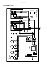
AREC4020/25E-208V

H1H2

N

Id

S

IR

e B1

E

C

Room

C2

C1

Actuator 230V Supply 230V

PE

L

N

He

ating

L

N

~

L

Tr

af

o

K

2

K

1

K

2

K

1

40

20

E/

4025E

!

X 20

8V

3~

TS

2

TS

1

M ot

or

pro

tectio

n

0-10

V

GND

PWM

L

N

M ot

or

Int

ern

al

sen

sor

M

M

M

M

20

8V

3~

L1

L2

L3

40

25

E/

4020E

40

20

: 6 

m

ot

or

s

40

25

: 7 

m

ot

or

s

L1 K

2

L2 K

2

L3 K

2

L1 K

1

L2 K

1

L3 K

1

TS

4

TS

3

L1 K

2

L2 K

2

L3 K

2

L1 K

1

L2 K

1

L3 K

1

PA

EC

/A

R

EC

 402

0E

/40

25E

161

12

3

AREC4000

18

Summary of Contents for 161054

Page 1: ...Seal The ratings shown are based on tests and procedures performed in accordance with AMCA Publication 211 and AMCA Publication 311 and comply with the requirements of the AMCA Certified Ratings Program The AMCA Certified Ratings Seal applies to airflow rate average outlet velocity outlet velocity uniformity velocity projection and power rating at free delivery only ...

Page 2: ... 3650 76 22 670 3 9 600V3 18 77 5 AREC4020E24 600VNA 8 24 5200 78 30 1008 6 2 600V3 24 101 5 AREC4025E30 600VNA 9 9 30 6200 80 36 1174 7 0 600V3 29 130 0 Type Output 4 kW Airflow 1 m3 h Sound power 2 dB A Motor power W Voltage motor V Amperage motor A Water volume l Weight kg AREC4010W NA 15 2325 76 503 208V1 3 0 1 87 52 AREC4015W NA 23 3350 76 670 208V1 4 0 2 96 71 AREC4020W NA 32 4650 78 1006 20...

Page 3: ... Nozzle depth and width mm Max velocity at nozzle m s Outlet velocity m s Outlet velocity uniformity AREC4010A AREC4010Exx 80x970 14 95 13 61 94 AREC4015A AREC4015Exx 80x1485 14 36 13 11 94 AREC4020A AREC4020Exx 80x1975 14 95 13 61 94 AREC4025A AREC4025Exx 80x2508 14 36 13 11 94 AREC4010W NA 80x970 13 55 12 54 90 AREC4015W NA 80x1485 12 68 12 16 96 AREC4020W NA 80x1975 13 55 12 54 90 AREC4025W NA ...

Page 4: ...12 125 AREC4015E18 600VNA 20 61 2150 76 22 670 3 9 600V3 18 171 AREC4020E24 600VNA 27 82 3050 78 30 1008 6 2 600V3 24 224 AREC4025E30 600VNA 34 102 3650 80 36 1174 7 0 600V3 29 287 Type Output 4 MBH Airflow 1 cfm Sound power 2 dB A Motor power W Voltage motor V Amperage motor A Water volume US gal Weight lb AREC4010W NA 51 1350 76 503 208V1 3 0 0 49 115 AREC4015W NA 78 1950 76 670 208V1 4 0 0 78 1...

Page 5: ...nly Type Nozzle depth and width in Max velocity at nozzle fpm Outlet velocity fpm Outlet velocity uniformity AREC4010A AREC4010Exx 3 1x38 2 2943 2679 94 AREC4015A AREC4015Exx 3 1x58 5 2827 2581 94 AREC4020A AREC4020Exx 3 1x77 8 2943 2679 94 AREC4025A AREC4025Exx 3 1x97 7 2827 2581 94 AREC4010W NA 3 1x38 2 2667 2469 90 AREC4015W NA 3 1x58 5 2469 2394 96 AREC4020W NA 3 1x77 8 2667 2469 90 AREC4025W ...

Page 6: ...8 0 39 10 3 AREC4025W NA max 5700 32 6 35 0 28 7 2 40 1 39 0 49 19 0 Metric chart Imperial chart 1 Recommended outlet air temperature for good comfort and optimized output 2 Nominal output at given supply and return water temperature Supply water temperature 176 F Room temperature 64 F Outlet air temperature 95 F 1 Water temperature 176 140 F Room temperature 64 F Type Fan position Airflow cfm Out...

Page 7: ...es EN Les pages de présentation contiennent principalement des images Pour la traduction des textes en anglais consultez la page correspondante à la langue souhaitée Las páginas introductorias contienen básicamente imágenes Consulte la traducción de los textos en inglés que las acompañan en las páginas del idioma correspondiente FR ES ...

Page 8: ... 82 68 AREC4020x D 2579 103 16 AREC4025x E 1020 40 80 AREC4010x F 1520 60 80 AREC4015x G 2020 80 80 AREC4020x H 2520 100 80 AREC4025x I 29 1 16 J 90 3 60 K 53 2 12 L 218 8 72 M 296 11 84 N 851 34 04 O 803 32 12 P 851 34 04 Q 20 0 80 A B C D J K M I I Q L N O P E F G H AREC4000 8 Metric Imperial 1 m 4 x M8 1 5 m 4 x M8 2 m 6 x M8 2 5 m 6 8 x M8 3 3 ft 4 x M8 4 9 ft 4 x M8 6 6 ft 6 x M8 8 2 ft 6 8 x...

Page 9: ...010x G 218 8 72 AREC4010x H 1400 56 00 AREC4015x I 851 34 04 AREC4015x J 945 37 80 AREC4020x K 851 34 04 AREC4020x L 1198 47 92 AREC4025x M 851 34 04 AREC4025x AREC4000 9 884 851 71 56 218 1400 851 851 851 945 1198 1198 945 ø29 ø20 ø29 Mounting on threaded bars outside the unit AREC4015x AREC4010x Top view AREC4020x AREC4025x A G H J L L J I K M C D D E F B ...

Page 10: ...AREC4000 10 Fig 1b Mounting on threaded bars outside the unit Mounting on threaded bars outside the unit Fig 1a Mounting brackets on delivery AREC4020x NA AREC4025x NA ...

Page 11: ...R 666 26 64 AREC4020x S 430 17 20 AREC4020x T 56 2 24 AREC4020x U 291 11 64 AREC4020x V 742 29 68 AREC4020x W 397 15 88 AREC4025x X 723 28 92 AREC4025x Y 340 13 60 AREC4025x Z 430 17 20 AREC4025x AA 56 2 24 AREC4025x AB 292 11 68 AREC4025x AC 828 33 12 AREC4025x AD 339 13 56 AREC4025x AREC4000 11 363 340 430 430 56 56 430 56 430 56 291 291 994 411 368 754 666 666 484 218 71 56 291 292 828 339 828 ...

Page 12: ... m 6 x M8 2 5 m 6 8 x M8 Fig 2 Mounting on threaded bars inside the unit Mounting on threaded bars inside the unit Metric Imperial 1 m 4 x M8 1 5 m 4 x M8 2 m 6 x M8 2 5 m 6 8 x M8 3 3 ft 4 x M8 4 9 ft 4 x M8 6 6 ft 6 x M8 8 2 ft 6 8 x M8 ...

Page 13: ...Fig 3 Snap fixings 90 AR Service hatch Fig 4 SIRe inside the unit Fig 5 Hoses are mounted via cable glands at knockouts to protect the hose and prevent air leakage AREC4000 13 1 2 AREC ...

Page 14: ...5x 4 pcs PA34CB20 AREC4020x 6 pcs PA34CB30 AREC4025x 8 pcs PA34VD15 AREC4010 15x 4 pcs PA34VD20 AREC4020x 6 pcs PA34VD30 AREC4025x 8 pcs FHDN2010 AREC4000W 2 pcs L 1 m L 3 3 ft AR42XTT10 AREC4010x H 130 210 mm H 5 2 8 4 in AR42XTT15 AREC4015x H 130 210 mm H 5 2 8 4 in AR42XTT20 AREC4020x H 130 210 mm H 5 2 8 4 in AR42XTT25 AREC4025x H 130 210 mm H 5 2 8 4 in PA34CB PA34TR PA34VD FHDN20 AR42XTT See...

Page 15: ...ReCC640 40 m 131 2 ft SIReCC403 3 m 9 8 ft SIReCC405 5 m 16 4 ft SIReCC410 10 m 32 8 ft SIReCC415 15 m 49 2 ft SIRe SIReAC SIReAA SIReRTX SIReWTA SIReCC SIReCJ4 SIReCJ6 Type Connection VLSP15NF NA DN15 1 2 VLSP20 NA DN20 3 4 VLSP25 NA DN25 1 VLP15NF NA DN15 1 2 VLP20 NA DN20 3 4 VLP25 NA DN25 1 VKF SDM24 ST23024 SD230 BPV10 VKF VLSP NA VLP NA Nipple G NPT Nipple G NPT AREC4000 15 ...

Page 16: ...SIRe B1EC Room C2 C1 Actuator 230V Supply 230V PE L N Heating L N L Trafo Motor protection 0 10V GND PWM L N Motor Internal sensor M M M M 4010WA 4025WA 4020WA 4015WA 208V1 PE L1 L2 AREC4000W A PAEC4000W A 161120 AREC4000 16 ...

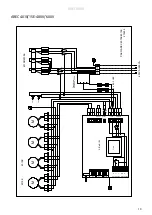
Page 17: ...C1 Actuator 230V Supply 230V PE L N Heating L N L Trafo K2 K1 4010E 4015E 4010E 4015E TS1 TS2 Motor protection 0 10V GND PWM L N Motor Internal sensor M M M M L1 L2 L3 L1 K2 L2 K2 L3 K2 L1 K1 L2 K1 L3 K1 PAEC AREC4010E 4015E 161121 208V3 AREC4000 17 ...

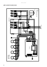
Page 18: ...K 1 K 2 K 1 4020E 4025E 2 X 208V3 TS 2 TS 1 Moto r p rotec tio n 0 10 V GND P WM L N Moto r Inte rna l se n so r M M M M 208V3 L1L2 L3 4025E 4020E 4020 6 motors 4025 7 motors L1 K 2 L2 K 2 L3 K 2 L1 K 1 L2 K 1 L3 K 1 TS 4 TS 3 L1 K 2 L2 K 2 L3 K 2 L1 K 1 L2 K 1 L3 K 1 PAEC A REC 4020E 4025E 161123 AREC4000 18 ...

Page 19: ... ctuato r 230V S upply230V PE L N He ating L N L Trafo K 2 K 1 4010E 4015E TS1 TS2 Motor protec tio n L N Motor Internal sensor M M M M 6 0 0 48 0V 230V Transformer 2 x 10A FUSE L1 L2 L3 2 3 1 PAEC AREC 4010E 4015E 215222 600V3 480V3 4010E 4015E AREC4000 19 ...

Page 20: ...eating L N L Trafo K2 K1 K2 K1 4025E 4020E 4020E 4025E 2 X 600V3 480V3 TS2 TS1 TS3 TS4 Motor p rotection 0 10V GND PWM L N Motor Internal sensor M M M M 600V3 480V3 600 480V 230V Transformer FUSE 2 x 10A L1L2 L3 4020 6 motors 4025 7 motors 2 3 1 2 3 1 PAEC AREC4020E 4025E 215223 AREC4000 20 ...

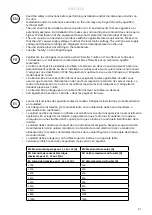
Page 21: ...cables Veuillez vous assurer que la tension d alimentation de l unité correspond à la tension de secteur locale La tension d alimentation de l unité et les calibres maximums sont indiqués sur l étiquette de données placée sur l unité L unité doit être protégée par un fusible conformément au tableau ci dessous Voir également la section Sécurité dans les pages en français Lea las instrucciones de se...

Page 22: ...ation of at least 3 mm 0 12 in should only be wired by a competent electrician and in accordance with the latest edition of IEE wiring regulations The control system is pre installed in the air curtain with an integrated control card SIRe is supplied pre programmed with quick fit connections Modular cables are connected to the control board Fig 4 See manual for SIRe 1 The service hatch is opened b...

Page 23: ...placed on the top and the side of the unit Hoses are mounted via cable glands at knockouts to protect the hose and prevent air leakage Fig 5 Adjustment of the air curtain and airflow The direction and speed of the airflow should be adjusted considering the load on the opening Pressure forces affect the airstream and force it inwards towards the premises when the premises are heated and the outdoor...

Page 24: ...d 5 Reconnect the unit All motors are equipped with an integral thermal safety cut out This will operate stopping the air curtain should the motor temperature rise too high The cut out will automatically reset when the motor temperature has returned to within the motor s operating limits Temperature control Temperature control of SIRe maintains the exhaust temperature If the temperature should exc...

Page 25: ...clean the appliance or perform user maintenance CAUTION Some parts of this product can become very hot and cause burns Particular attention has to be given where children and vulnerable people are present Residual current circuit breaker E When the installation is protected by means of a residual current circuit breaker which trips when the appliance is connected this may be due to moisture in the...

Page 26: ......

Page 27: ......

Page 28: ...AB Tel 46 31 336 86 00 Industrivägen 41 SE 433 61 Sävedalen mailbox frico se Sweden www frico net For latest updated information and information about your local contact www frico net Art no 189847 KG 13 December 2021 ...

Reviews: