070.655-IOM (FEB 22)
Page 22
SBTP Rotary Screw Compressor
Maintenance
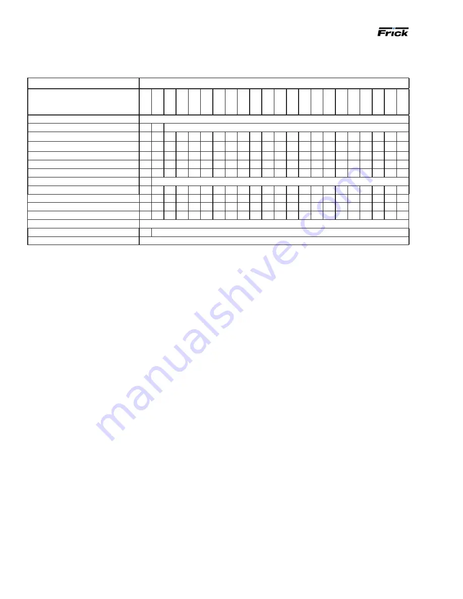
Maintenance schedule
Follow this schedule to ensure trouble-free operation of the compressor unit.
Frequency or hours of operation, maximum
Maintenance
200
1000
5000
8000
10
,000
15
,000
20
,000
25
,000
30
,000
35
,000
40
,000
45
,000
50
,000
55
,000
60
,000
65
,000
70
,000
75
,000
80
,000
85
,000
90
,000
95
,000
Change oil
As directed by oil analysis
Oil analysis
Every 6 months
Replace oil filters
Clean oil strainers
Clean liquid strainers
Replace coalescers
Check and clean suction strainer
Check coupling
Annually regardless of operating hours
Check alignment
Suction and discharge flange bolts
Check electrical connections
Check sensor calibration
Test high pressure cut-out
Test annually
Vibration analysis
Every 6 months, more frequently if levels increase
Replace shaft seal
When leak rate exceeds 20 drops per min
Vibration analysis
Periodic vibration analysis can be useful in detecting bear-
ing wear and other mechanical failures. If you are using
vibration analysis as part of your preventive maintenance
program, take the following guidelines into consideration:
• Always take vibration readings from exactly the same
places and at exactly the same percentage of load.
• Use vibration readings taken from the new unit at
start-up as the baseline reference.
• Evaluate vibration readings carefully because the in-
strument range and function used can vary, which can
easily lead to misinterpreting findings.
• Other equipment operating in the vicinity or connected
to the same piping as the unit can influence vibration
readings.
• If using proximity probes, collect data and evaluate
periodically in the same manner as vibration readings.
Oil quality and analysis
High quality and suitable oil is necessary to ensure com-
pressor longevity and reliability. Oil quality rapidly dete-
riorates in systems containing moisture and air or other
contaminants. In order to ensure the quality of the oil in
the compressor unit, adhere to the following points:
• Only use Frick oil or high quality oils approved by John-
son Controls-Frick for your application.
•
Only use Frick filter elements. Substitutions must be
approved in writing by Johnson Controls-Frick engi-
neering or warranty claim may be denied.
• Participate in a regular, periodic oil analysis program to
maintain oil and system integrity.
Operating log
Using an
permits thorough analysis
of the operation of a system by those responsible for its
maintenance and servicing. Continual recording of gauge
pressures, temperatures, and other pertinent information
enables the observer and serviceman to be constantly
familiar with the operation of the system and to recognize
immediately any deviations from normal operating condi-
tions. Frick suggests to take readings at least daily.
Notes:
• When checking the coupling, check bolts, shim packs, center inserts, keys, and all bolt torques.
•
For suction and discharge flange bolts, verify the tightness of the bolts.
•
For electrical connections, check and torque all terminals in the processor and starter panel as shown in the specification posted in the
enclosure.
• For senor calibration, check the calibration of the slide valve, slide stop, pressures and temperatures. Conduct calibration with
NIST- certified devices.
• For vibration analysis, baseline vibration analysis is required during initial commissioning. Vibration measurement must be carried out con-
tinuously to obtain optimum preventive control on bearings.
•
When replacing oil filters, the filter may need to be changed more frequently based on differential pressure or as directed by oil analysis.
• When checking alignment, refer to
070.210-IB, Screw Compressor Foundations
for foot-mounting alignment.


