Frick QUANTUM HD Installation Operation & Maintenance Download Page 6

QUANTUM™ LX/HD SYSTEM INTERFACE PANEL

INSTALLATION-OPERATION-MAINTENANCE

090.030-IOM (OCT 13)

Page 6

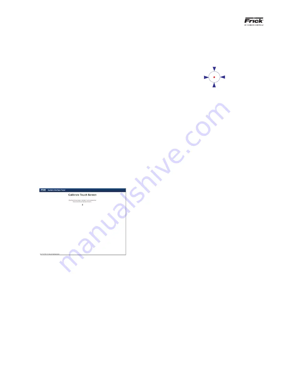
4.  Pressing anywhere on the screen within the 

fi

 ve 

second countdown will cause the screen to show 

the following image in the upper left corner:

5.  Notice that the symbol collapses and expands. 

Try to touch the red dot within the circle as 

closely as possible. When the screen senses your 

touch, the symbol will move to its next calibra-

tion point. Continue to touch the red dot at each 

new location.

6.  After the last calibration point has been touched, 

the screen is now calibrated, and will either re-

turn to the Con

fi

 guration screen (if this is where 

the calibration was initiated from, or it will 

fi

 nish 

the boot process if calibration was initiated dur-

ing power cycle.

NOTE:

 If, for any reason, after completing the calibration, 

the cursor still does not appear where it should be, the 

calibration will need to be repeated.

Proper calibration is very important to ef

fi

 cient screen opera-

tion, especially when utilizing the on-screen keyboard. If the 

touch screen is out of a calibration, it can mean that the area 

being touched is actually being applied somewhere else, which 

can translate into the wrong button keyboard button being 

sensed, or the wrong setpoint area detected.

Touch Screen Calibration 

As the SIP comes from the factory, calibration has already 

been performed, and as such, should not be needed. How-

ever, it is possible that from time to time, re-calibration 

may be warranted. If the cursor does not move to your 

fi

 nger when you touch the screen, then the touch screen 

should be re-calibrated.

There are two methods by which the screen may be cali-

brated. One is to perform a power cycle, the other is to 

access the screen calibration button (this second method 

will be described in the 

Con

fi

 guration  Page

 section, de-

scribed later). 

To perform a power cycle:

1.  Turn the Control Power switch to off.

2.  Wait several seconds, then turn the Control 

Power switch back on.

3.  The display will show a series of boot screens, 

then the HD logo will appear. Following the HD 

logo screen, a prompt will appear for 5 seconds, 

allowing access to the Screen Calibration fea-

ture:

CALIBRATING THE SIP

Summary of Contents for QUANTUM HD

Page 1: ...PERATION MAINTENANCE FRICK QUANTUM LX HD SYSTEM INTERFACE PANEL Version 2 0x Form 090 030 IOM OCTOBER 2013 INSTALLATION OPERATION MAINTENANCE File SERVICE MANUAL Section 90 Replaces 090 030 O MAR 12 D...

Page 2: ...Assembly 18 Display Replacement 18 Touch Screen Description 19 Using a Mouse 19 Power Supply 20 SIP Replacement Parts 21 Wiring Schematic 22 Warning The Quantum LX and HD Controllers has the capabilit...

Page 3: ...stem Interface Panel or SIP Two versions of the Quantum control panel are compatible with the System Interface Panel the Quantum LX and the Quantum HD Typical Compressor Package The following informat...

Page 4: ...ght Ethernet cables are the straight pin to pin variety and work in most configurations However if you want to connect two Ethernet devices directly together in this case one SIP to one Quantum LX or...

Page 5: ...l door and locating the Q4 controller as shown here Ethernet Connector Q4 Processor Plug one end of the cable into the port as labeled Route the cable out of the box and to the point at which it will...

Page 6: ...ecially when utilizing the on screen keyboard If the touch screen is out of a calibration it can mean that the area being touched is actually being applied somewhere else which can translate into the...

Page 7: ...s provides a menu to navigate between pages List Selecting this from any screen will return you to the List screen Manage Selecting this will allow you to configure all of the devices that will be con...

Page 8: ...t in the upper left corner of this icon indicates that the unit is operating normally and has no active alarms The yellow dot in the upper left corner of this icon indicates that the unit has an activ...

Page 9: ...oard will appear Use this keyboard to enter a unique name that helps to describe the location or function that applies to the panel being added The Name is tied with the IP ad dress As each IP address...

Page 10: ...te the Manage Panels page The Cancel button will void all changes and return you to the Add Pages screen Once a panel or panels have been added they will now appear on the Manage Panels page Actions S...

Page 11: ...Manage Tags page to change the names of Work Groups as they appear on the List page Work Group tag names are cus tomizable names that can be created to allow for grouping of similar product panels Ta...

Page 12: ...NTERFACE PANEL INSTALLATION OPERATION MAINTENANCE 090 030 IOM OCT 13 Page 12 ABOUT Page g This page provides information about the panel These pieces of information will be necessary if factory assis...

Page 13: ...e IP addresses a subnet mask contains four bytes 32 bits and is often written us ing the same dotted decimal notation Subnet masks accompany an IP address and the two values work together Applying the...

Page 14: ...tive alarms will be shown within the button All configured panels will be listed on this page each panel will be shown on it s own row Notice that there is a PLUS symbol at the beginning of each row S...

Page 15: ...described in the What Should Occur When Ap plying Powering section If the powering up sequence continues to repeat without displaying the List page then there is a booting problem 3 Check all plugged...

Page 16: ...ngle symbol denotes Pin 1 on connectors Refer to the chart on the following page for jumper settings NOTE 2 Do NOT remove the CN4 jumper Removal of this jumper will cause the processor to not power up...

Page 17: ...x600 6 4 2 5 3 1 1 3 Closed 4 6 Closed JLVDS3 Backlight Control Mode Voltage Mode 1 2 3 1 2 Closed 18 bit 640x480 6 4 2 5 3 1 3 5 Closed 4 6 Closed PWM Mode Pulse Width Modulation default 1 2 3 2 3 Cl...

Page 18: ...r with the relocation of this connector 3 Remove the six nuts that mount the display plate to the door 4 Carefully lay the display plate down on a table or bench with the display side up 5 Loosen the...

Page 19: ...active areas of the display for the purpose of changing setpoints selecting menus and accessing other operational features If for any reason the touch screen either doesn t re spond to your touch or...

Page 20: ...communications failures Q5 reboots for no apparent reason LED s on the Q5 are lit but nothing appears on the display To perform measurements and adjustment on the power supply voltage use a reliable c...

Page 21: ...ndoor 649D6101G01 1032704 Touchscreen glass w overlay of Frick logo Flash Cards and Software 639A0290G07 1073320 Quantum SIP Program Flash Card Version 2 00 Harnesses 639B0116H01 677556 DC power I O C...

Page 22: ...QUANTUM LX HD SYSTEM INTERFACE PANEL INSTALLATION OPERATION MAINTENANCE 090 030 IOM OCT 13 Page 22 Wiring Schematic...

Page 23: ...QUANTUM LX HD SYSTEM INTERFACE PANEL INSTALLATION OPERATION MAINTENANCE 090 030 IOM OCT 13 Page 23...

Page 24: ...e 24 Form 090 030 IOM 2013 10 Supersedes 090 030 O MAR 12 Subject to change without notice Printed In USA GUI 1M 20 2013 Johnson Controls Inc ALL RIGHTS RESERVED JOHNSON CONTROLS 100 CV Avenue P O Box...

Reviews: