


Descriptions of LEFT and RIGHT are from the point of view of standing
behind the equipment facing the front
23
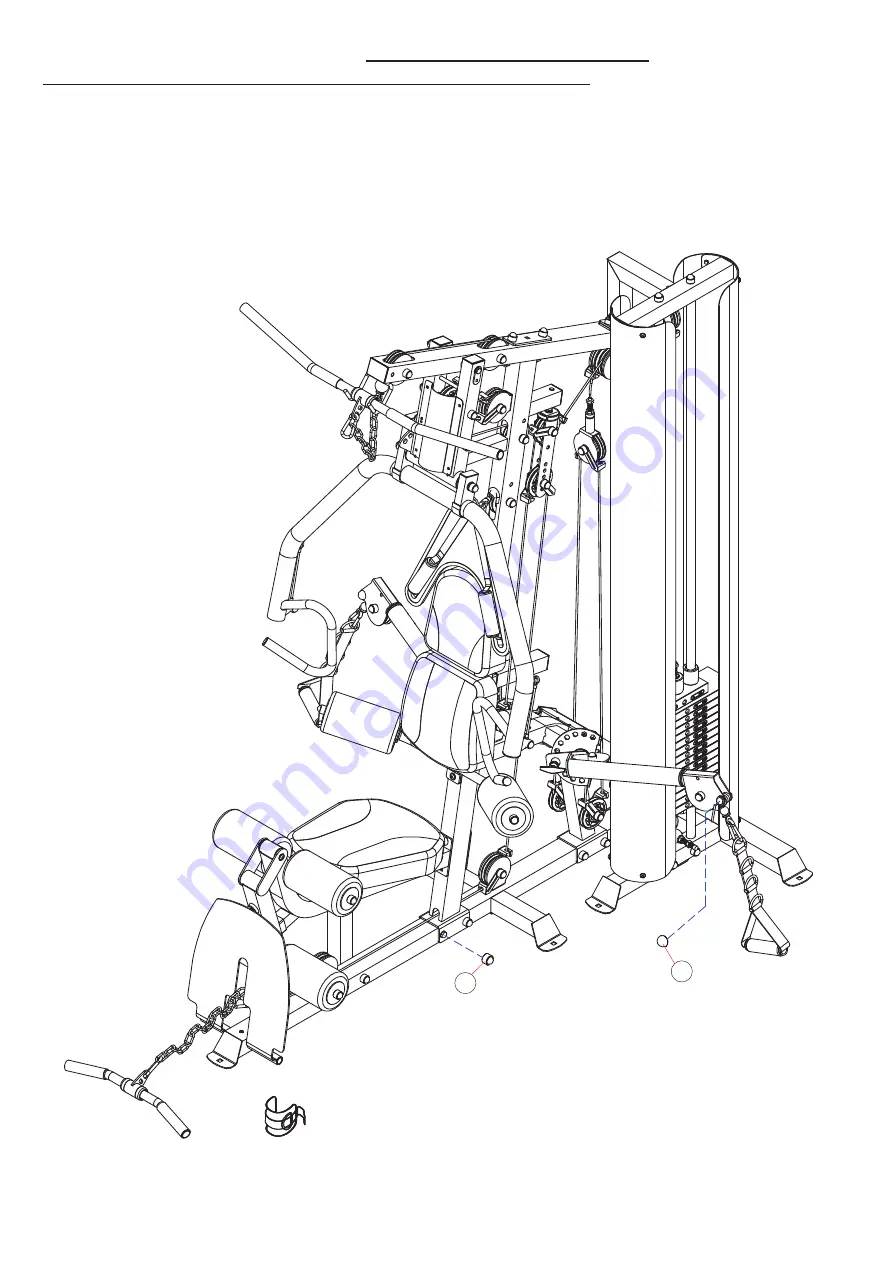
ASSEMBLY DIAGRAM 1
USE A PARTNER TO HELP WITH THIS STEP
REMEMBER: Only hand tighten all nuts and bolts until whole
&&Ͳ
X
ϰ
is assembled
1.
Once the nuts and bolts are all correctly attached and tightened, cover them with the one hundred and four
COVER CAPS M10 (87) and the four COVER CAPS M8 (88)
2.
Insert all the correct sized END CAPS into any open ends.
3.
Insert a STOPPER (63) and WASHER (94) onto the front of the FRONT SUPPORT FRAME (6) and the front of the FRONT
VERTICAL FRAME (3)
(For greater detail
–
see the expanded diagram, skip this step if pre-assembled)