background image

Installing Instruction

1.

Connect the left riser (11) to the left bottom tube (1) using M10*90 outer hexagonal bolts, and fasten with M10

lock nuts.

2.

Connect the right riser (12) to the right bottom tube (2) using M10*90 outer hexagonal bolts, and fasten with

M10 lock nuts.

3.

Connect the counterweight guiding tube (5) to the left bottom tube (1), and connect the counterweight guiding

tube (5) through the left bottom supporting tube (3) with M10*20 hexagonal bolts.

4.

Connect the counterweight guide tube (5) to the right bottom tube (2), and connect the counterweight guiding

tube (5) through the right bottom supporting tube (4) with M10*20 hexagonal bolts.

5.

Install the shock absorber (6), counterweight bottom piece (7) and counterweight top piece (8) to the

counterweight guiding tube (5) successively.

6.

Connect the lifting rod (9) to the counterweight top piece (8) tightly. Install the adjusting wheel frame (10) on

top of the lifting rod (9).

7.

Install the fixing guiding tube (13) to the counterweight guiding tube (5) and fasten it with M10*20 hexagonal

bolts.

8.

Connect the left riser (11) with the left riser (11) and the right riser (12) with M10*70 outer hexagonal bolts,

and fasten them with M10 lock nuts.

9.

Connect the upper crossbeam tube (14) to the left riser (11) and the right riser (12) with M10*70 outer

hexagonal bolts, and fasten them with M10 lock nuts.

10. Install the rear riser (15) on the left bottom tube (1) and right bottom tube (2) with M10*90 outer hexagonal

bolts, and fasten them with M10 lock nuts.

11. Connect the rear riser (15) to the fixing guiding tube (13) using M10*70 outer hexagonal bolts, and tighten

with M10 lock nuts.

12. Use M10*10*70 hexagonal bolts to pass through the rear connecting tube (16) and the rear riser (15),

connect with the pendant tube (17), and fasten with M10 lock nuts.

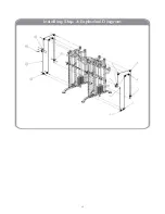
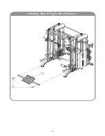
Installing Step 1 Assembling Diagram

12

Summary of Contents for FF-FSR90

Page 1: ...FF FSR90 ASSEMBLY MANUAL MULTI FUNCTIONAL TRAINER SMITH RACK SYSTEM 1...

Page 2: ...ax Load Smith Bar 600 lbs Max Load Plate Storage 600 lbs Max Load Pull Up Bar 1100 lbs Weight 992 lbs 450 kgs 2 220 lb weight stacks 2 1 Ratio Weight Stacks Feel Like 110 lbs per side due to pulley ra...

Page 3: ...imple to do Just repeat a small amount of warm up activities Use the right way Focus on working out the muscle groups used in the exercise you are doing If other muscles are also involved you may need...

Page 4: ...n both of your legs with one behind the other lean forward and put your hands against the wall Straighten the leg at the back and keep the foot flat on the floor Bend the leg at the front lean forward...

Page 5: ...ugh your mouth To avoid injury to the spine please maintain the correct postures Please concentrate on exercising your muscles throughout your fitness process After exercise Please take a day off afte...

Page 6: ...ht plates Cantilever connecting rod Free training handle Single and parallel bars hanging parts Smith safety group Foot pedal assembly Lanyard hook Lat pull knee cushion Pull up handle Smith hook Squa...

Page 7: ...eweldment 1 Rearriserweldment 2 Middleriser rightwelding 1 Middleriser leftwelding 1 Hangingtubeweldment 1 Connectingrodweldment 1 Uppersupportingtube left welding 1 Uppersupportingtube right welding...

Page 8: ...ngsleevetubeweldment 2 Pulleypieceweldment 2 Linearbearingsleeveweldiment 2 Adjustablefoottubeleftwelding 1 Adjustablefoottuberightwelding 1 Pullingbar1weldment 1 Dropbar 1 Terminationhookplate2 4 Ter...

Page 9: ...be1weldment 1 Olympicrodtrainingrack tube2weldment 1 Olympicrodhookweldment 2 Parallelbartube rightweldment 1 Parallelbartube leftweldment 1 Foamsupportweldment 1 Foamtubeweldment 1 Barbellrodconnecti...

Page 10: ...icropehanginghook chrome plated 2 19guidingrodweldment 4 length 1775 F50stainlesssteelrightadjustment tube 1 length 1880 F50stainlesssteelleftadjustment tube 1 length 1880 Bearingsteel 2 6010OlympicBa...

Page 11: ...Installing Step 1 Exploded Diagram 11...

Page 12: ...d 9 to the counterweight top piece 8 tightly Install the adjusting wheel frame 10 on top of the lifting rod 9 7 Install the fixing guiding tube 13 to the counterweight guiding tube 5 and fasten it wit...

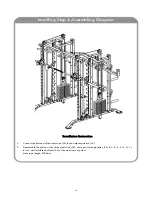
Page 13: ...Installing Step 2 Exploded Diagram 13...

Page 14: ...the adjusting sleeve tube 19 using the rotating shaft 21 and fasten with M10 hexagonal bolts 5 Install the hook plate 22 on the left riser 11 and right riser 12 using M10 90 outer hexagon bolts and f...

Page 15: ...Installing Step 3 Exploded Diagram 15...

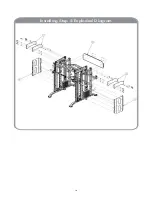
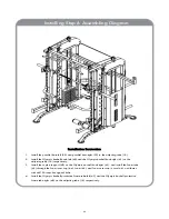
Page 16: ...Olympic barbell fixing sleeve 28 and sliding rod fixing sleeve 30 successively 3 Connect the Olympic barbell fixing sleeve 28 with the Olympic barbell 25 and connect the sliding rod fixing sleeve 30...

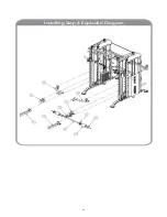
Page 17: ...Installing Step 4 Exploded Diagram Installing Step 4 Exploded Diagram 17...

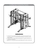
Page 18: ...ope 32 to the adjusting sleeve 19 2 Disassemble the ball end 34 of the steel rope 32 and pass it through pulley 33 B C D E F G H I J in turn and install the ball end 34 of the steel rope at point J St...

Page 19: ...Installing Step 5 Exploded Diagram 19...

Page 20: ...nd connecting decorative plate 37 respectively and fasten with M10 lock nuts 2 Pass the M8 20 outer hexagonal bolts through the guard 35 and fix them on the left riser 11 and rear riser 15 respectivel...

Page 21: ...Installing Step 6 Exploded Diagram 21...

Page 22: ...8 respectively 3 Install the supine support 42 on the Olympic barbell hook right 41 and install the foam tube 43 through the foam inner cap 44 foam 45 and foam outer cap in turn 46 and fasten with M8...

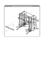
Page 23: ...Installing Step 7 Exploded Diagram 23...

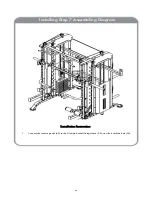
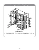
Page 24: ...Installation Instruction 1 Connect the reverse pedal 49 to the Olympic barbell fixing sleeve 28 and fix it with the bolt 50 Installing Step 7 Assembling Diagram 24...

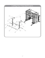
Page 25: ...Installing Step 8 Exploded Diagram 25...

Page 26: ...Installation Instruction 1 Connect the auxiliary foot pedal 51 to the left bottom tube 1 and the right bottom tube 2 and fix with the bolt 50 Installing Step 8 Assembling Diagram 26...

Page 27: ...Installing Step 9 Exploded Diagram 27...

Page 28: ...lts 3 Install the barbell cover 57 on the arm swinging left 53 and arm swinging right 54 respectively with M10 20 outer hexagonal bolts 4 Install the handles 56 on the arm swinging left 53 and arm swi...

Reviews: