background image


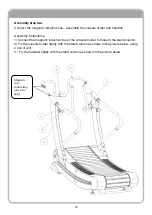
Assembly step one: 
 

Connect the magnetic induction line and assemble the stand column. 
Assembly instructions: 
1) Remove the packing materials on both sides of the stand column. 

2) Fix the stand column to the corresponding position of the main frame as shown in 
the picture below. 
Note: Connect the magnetic line below. 


Magnetic 
wire 
connecting 
(one wire 
only) 
 

 Connect up 
and down  
(one wire 
only) 
 

Summary of Contents for FF-CT80

Page 1: ...1 FF CT80 FRENCH FITNESS CT80 MANUAL CURVE TREADMILL W RESISTANCE ASSEMBLY MANUAL...

Page 2: ...rate and maintenance cost Eliminates the slippage of traditional running belts Accurate speed no block or cover of running area wider field of vision easier for gait analysis 8 Resistance Levels Run a...

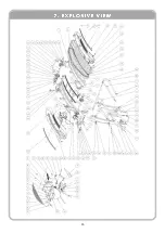
Page 3: ...3 1 SAFETY CAUTIONS 4 2 TECHNICAL STANDARD 6 3 MACHINE DIAGRAM 7 4 INSTALLATION PROCEDURES MACHINE DEBUG 8 5 OPERATION GUIDE 12 6 PACKING LIST 14 7 EXPLOSIVE VIEW 15 8 PARTS LIST 16...

Page 4: ...the event of an emergency stop the machine immediately 5 It is forbidden to let two or more people stand on the treadmill at the same time the maximum load weight is 170 kg 6 The heart rate sensor is...

Page 5: ...me before you start to use the treadmill If any of them is loose please change or fixed it 13 There must be the mark of Stop in maintenance 14 If there is abnormal noise or other abnormal situation of...

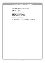
Page 6: ...four cell dry battery Time 0 00 99 59 Distance 0 00 99 99 km Calories 0 999 kcal Heart rate 60 300 beats min Rotating speed 0 90 KM H Resistance adjustment level 1 8 at1 the resistance is 0 at 8 the...

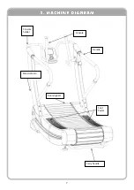
Page 7: ...7 Handle Console Running belt Foot Pedal Console holder Stand column Carry handle...

Page 8: ...nd ensure there is enough space around it Place all parts of the treadmill in the empty area and remove all packing materials Do not discard the packing materials until the assembly work is completed...

Page 9: ...ly instructions 1 Remove the packing materials on both sides of the stand column 2 Fix the stand column to the corresponding position of the main frame as shown in the picture below Note Connect the m...

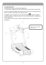
Page 10: ...ions 1 Connect the magnetic induction line of the console holder to those in the stand column 2 Fix the console holder tightly with the stand column as shown in the picture below using 2 pcs of 27 3 F...

Page 11: ...ole at the joint of console holder and fasten it as shown using 4pcs of 13 and 4pcs of 14 3 Stepping on the running belt run it and press the button to start the treadmill check the machine is running...

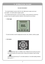
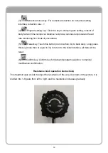
Page 12: ...purpose of use the specific operation methods of the treadmill are as follows 1 Home page The main interface is used to display device name time distance calories speed 2 Six button 1 Start Stop butt...

Page 13: ...procedures 5 Reset key Touch this button no more than 3s to back step Long press this key more than or equal to 3s to return to the initial interface all data will be reset 6 Confirm key Confirm key...

Page 14: ...1 Main frame assembly one piece 2 Right side stand column handrail one piece 3 Left side stand column handrail one piece 4 Console welding assembly one piece 5 Console one piece 6 Whole Screw one pie...

Page 15: ...15...

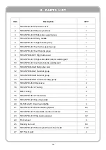
Page 16: ...side handle welding part 1 11 TZ04 SP03B 0420 Belt pulley rack 1 12 TZ04 SP03B 0421 handrail group 1 13 TZ04 SP03B 0422 handrail group 1 14 TZ04 SP03B 0423 condole welding group 1 15 TZ06 SP03 0603 B...

Page 17: ...3B 0250 Aluminum plate fixed sheet metal 1 39 TZ03 SP03B 0333 Set screw 1 40 TZ03 SP03B 0328 Small pulley 1 41 TZ03 SP03B 0327 Big pulley 1 42 TZ03 SP03B 0331 Support column 3 43 TZ03 SP03B 0332 Space...

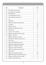
Page 18: ...1 Washer 2 69 M12X30L N1 Hexagon socket cap screws 2 70 M6X8L J1 Set screw 12 71 M8X16L N2 Hexagon round screw 8 72 M10X100L N1 Hexagon socket cap screws 2 73 8X14 Flat key 2 74 M10X15L N2 Hexagon rou...

Page 19: ...95 M8X16L N1 Hexagon socket cap screws 7 96 M10X50 Set screw 1 97 8X20 N Set screw 1 98 12 6 6 1 0t C1 Washer 8 99 M6X50L N1Hexagon socket cap screws 1 100 M6X6t S1 locknut 1 101 6001 Bearing 2 102 M8...

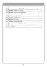
Page 20: ...side protecting case 1 114 TZ06 SP03 0611 Decorative ring 2 115 TZ06 SP03 0607 left front cover 1 116 TZ06 SP03 0608 left back cover 1 117 TZ06 SP03 0616 Console 1 118 TZ06 SP03 0609 Left side trim s...

Reviews: