P
a
g
e
| 42 of 44
FREMCO A/S
ELLEHAMMERVEJ 14
|
DK9900 FREDERIKSHAVN, DENMARK
VAT NO.: DK30815416
TEL45 7230 1213
[email protected]
WWW.FREMCO.DK
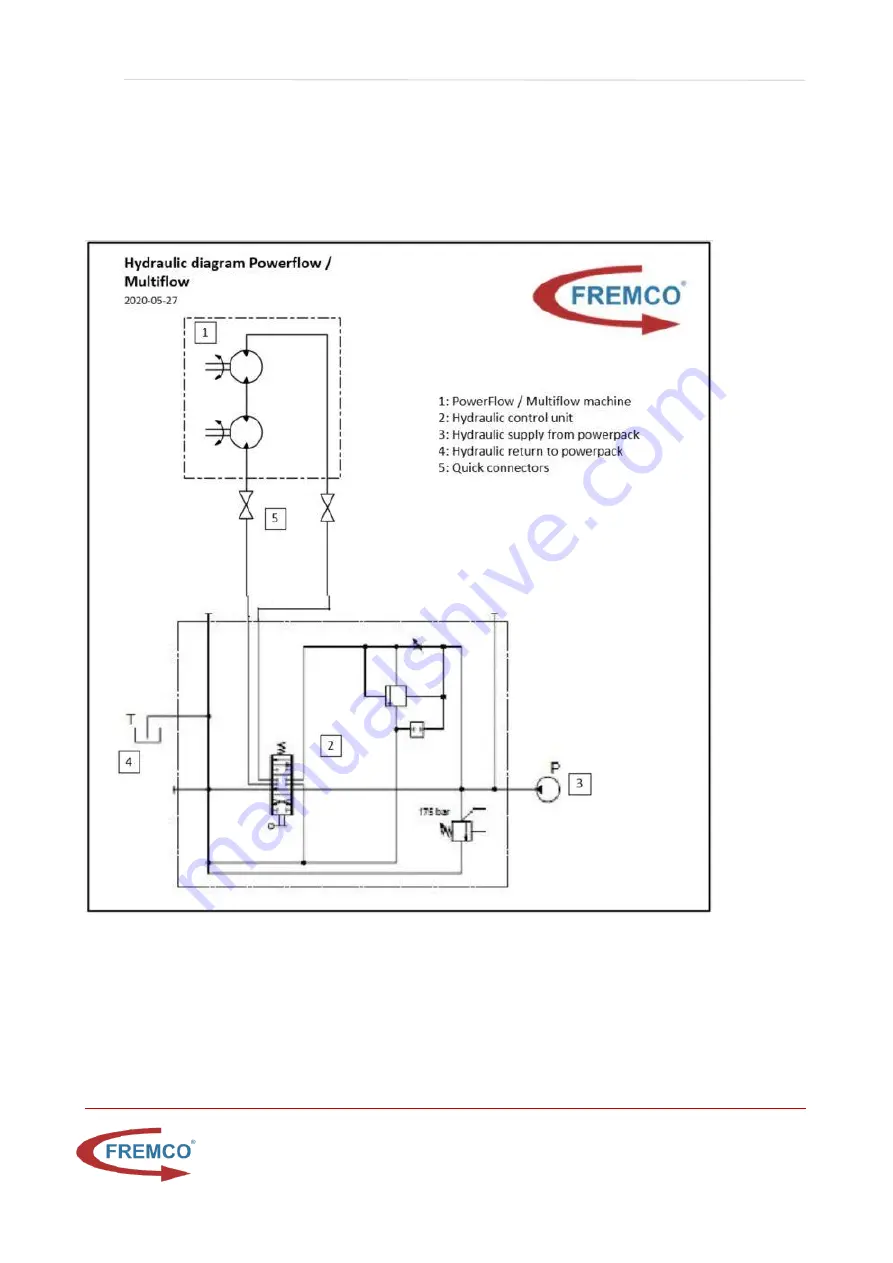
13. APPENDIXES
13.1. HYDRAULICS SCHEMATICS
Page 1: ...E 45 7230 1213 SALES FREMCO DK WWW FREMCO DK THIS MATERIAL IS COPYRIGHT PROTECTED Operating manual Responsible manufacturer Fremco A S Machine PowerFlow RAPID MultiFlow RAPID This is the original oper...
Page 2: ...SAFETY MEASURES 13 4 1 1 SAFETY FUNCTIONS 13 4 2 WARNING FORESEEABLE MISUSE 14 4 3 SAFETY MEASURES TO BE TAKEN BY THE USER 14 4 3 1 CLOTHING AND PERSONAL PROTECTIVE EQUIPMENT PPE 14 4 3 2 HANDLING OF...
Page 3: ...LEANING 28 8 2 2 CORRECTIVE MAINTENANCE 28 8 2 3 REPAIR 29 8 3 SERVICE AND REPAIR ADDRESS 29 8 4 DISCONNECTION AND DEPRESSURIZATION OF ENERGY SOURCES 29 8 5 MAINTENANCE SCHEDULE 30 8 5 1 VISUAL INSPEC...
Page 4: ...AMMERVEJ 14 DK9900 FREDERIKSHAVN DENMARK VAT NO DK30815416 TELEPHONE 45 7230 1213 SALES FREMCO DK WWW FREMCO DK 13 APPENDIXES 42 13 1 HYDRAULICS SCHEMATICS 42 13 2 PNEUMATICS SCHEMATICS 43 13 3 DRAWIN...
Page 5: ...tically included when you purchase your Fremco fiber blowing machine you automatically get our 12 months warranty You can then claim your additional 24 months warranty at any point during the followin...
Page 6: ...e from machine serial number 9328 3649 PowerFlow RAPID 9328 3748 MultiFlow RAPID Accessibility The instructions are to be kept in a location known to the staff and must be easily accessible for the op...
Page 7: ...s manufactured by Company name Fremco A S Company address Ellehammervej 14 DK 9900 Frederikshavn 2 2 THE MACHINE S DESIGNATION The machine s complete designation is PowerFlow RAPID or MultiFlow RAPID...
Page 8: ...K9900 FREDERIKSHAVN DENMARK VAT NO DK30815416 TELEPHONE 45 7230 1213 SALES FREMCO DK WWW FREMCO DK 2 4 MACHINE MARKINGS The machine is equipped with the following safety markings Hand crush hazard sym...
Page 9: ...3 Up to 5 000 m 16404 ft Floating distance3 Up to 10 000 m 32808 ft Blowing speed3 Up to 80 m min 262 ft Pushing force 0 125 kg 0 275 Ibs Max pressure and airflow4 16 bar 232 psi 8 000 12 000 l min 28...
Page 10: ...Up to 5 000 m 16404 ft Floating distance3 Up to 10 000 m 32808 ft Blowing speed3 Up to 80 m min 262 ft Pushing force 0 200 kg 0 440 9 Ibs Max pressure and airflow4 8 12 bar 116 174 psi 8 000 12 000 l...
Page 11: ...EMCO DK 3 3 HYDRAULIC CONTROL UNIT Manufacturer Fremco A S Ellehammervej 14 9900 Frederikshavn Denmark Item No 103 10041 Hydraulic connection 0 125 bar 17 l min Max pressure 125 bar Manometer 160 bar...
Page 12: ...ure should not exceed 8 C above the ambient temperature HYDRAULICS Oil consumption 17L oil per minute at max 110 bar Filtrated to below 25 m NOISE Airborne noise emitted by the machine Measured sound...
Page 13: ...as a hold to run system This means that the operator must perform a continuous actuation on the joystick on the hydraulic control unit in order for the machine to produce movement If the actuation ce...
Page 14: ...unctions are active and functional The operator must NOT under any circumstances Reach into touch the chain drive while the machine is in operation Exceed the maximum supply pressure of hydraulic cont...
Page 15: ...d when handling heavy parts 4 3 2 HANDLING OF DANGEROUS SUBSTANCES AND MATERIALS Chemicals and hydraulic fluids PPE must be used in accordance with the individual product s safety data sheets when Han...
Page 16: ...and gloves are worn when connecting and disconnecting hydraulic components Protective glasses and protective gloves are worn when servicing hydraulic components All machine components and energy suppl...
Page 17: ...ine is constructed for blowing fiber optic cables into microducts MultiFlow RAPID can also be used to reline multiple microducts The machine may only be used for these exact purposes PowerFlow RAPID h...
Page 18: ...ext to the control unit During maintenance and repair The area adjacent to the machine should also be considered as the workstation Space requirements There must be sufficient space in the workplace f...
Page 19: ...of max hydraulic oil pressure 110 BAR 1595 PSI Enables speed and torque adjustment Handle moves forward backwards Attach the end of the hose with the yellow markers to the hydraulic unit Air valve Co...
Page 20: ...se The EU DIN 3238 claw coupling is mounted by default The US claw can be found in the box Safety valve Pressure relief valve Set to release pressure above 16 BAR 230 PSI Handle for spindle Rotate clo...
Page 21: ...the speed of fiber passing the counter Blue button resets total meter counter 5 5 MACHINE ASSEMBLY AND ADJUSTMENT Parts in the Flex block RAPID Duct holder inserts and adaptors are chosen according to...
Page 22: ...is mounted properly the lock mechanism will be shown Picture 3 To dismount the Flex block RAPID repeat the process backwards 1 2 3 4 Adjusting the Flex block RAPID Before any fiber blowing job ensure...
Page 23: ...loosened moved away Pull the round hand knob on top of the flex block RAPID upwards and and pull away from the operational side to open the flex block RAPID Picture 2 Now continue with the duct holde...
Page 24: ...he machine s use handling etc through reviewing the operating manual operating instructions and workplace instructions Operators must be familiar with the location of secure access ways 6 2 MAINTENANC...
Page 25: ...ational requirements and regulations Before initiating fiber blowing it is important that the operator fixes the machine on e g a trolley or a box 7 2 START STOP Before initiating operation the operat...
Page 26: ...K HYDRAULICS CONNECTED HYDRAULICS DISCONNECTED When looking at the control valve it is marked on the sticker how to make the fiber cable go forward and reverse Use the hand knobs to adjust the maximal...
Page 27: ...with a fiber optic cable by passing it through the inlets chain drive and Flex block RAPID before turning on the machine After the fiber blowing has been completed the fiber optic cable is manually r...
Page 28: ...tra caution when the machine is in operation if they have disassembled the machine or are handling spare parts or tools Following completion of maintenance or repair the operator must check if the mac...
Page 29: ...or are handling spare parts or tools 8 3 SERVICE AND REPAIR ADDRESS In the case of defects or need for repairs covered by warranty please contact either the designated reseller in your country or Fre...
Page 30: ...ection and maintenance schedule If wear and tear parts are defective or worn to an extend that is unacceptable these parts should be replaced fixed before continued use Daily inspection and maintenanc...
Page 31: ...Instructions 1 Ensure the chains and chain support rail are sufficiently lubricated See description 7 5 3 Lubrication of the chains and chain support rail 2 Check the chain adjustment See description...
Page 32: ...tartup and with energy sources disconnected quick couplings Task Instructions 1 Check the safety functions Ensure that the hold to run function works as intended and the machine stops when the control...
Page 33: ...hain support rail along the full length of the support rail and on both sides of chains top and bottom 8 5 4 CHAIN ADJUSTMENT Adjust the chains using the two sets of chain tensioning screws The chain...
Page 34: ...nd sprockets must be replaced Indications of worn chains and sprockets The chains have clear and deep wear marks from the chain support rail The rubber on the chains have large deformations on the fro...
Page 35: ...coat of grease onto the threads before screwing the spindle handle down again Pump grease into the two grease nipples using a suitable grease gun Use one or two pumps for each nipple Finish by wiping...
Page 36: ...rough the designated reseller in your country Nylon seals Nylon seals come are available in multiple sizes Wear and tear parts can be ordered through the designated reseller in your country Air water...
Page 37: ...D MultiFlow RAPID o Airflow 8000 12000 l min o Pressure 8 12 bar Never exceed the recommended air pressure 2 Take note of the distance marking on the fiber cable 3 Do not use a fiber cable that fill t...
Page 38: ...e at the desired depth See guideline on FlowLUB 2 Add desired amout of FlowLUB 3 Apply one more sponge creating three layers with sponges and lubrication 4 Add air pressure pushing sponges and FlowLUB...
Page 39: ...ore dismantling the machine a plan must be prepared detailing this purpose The plan must include a risk assessment for the work as well as for the disposal of machines and machine parts 10 2 SCRAPPING...
Page 40: ...100 2011 Safety of machinery The standard specifies basic terminology principles and a methodology for achieving safety in the design of machinery It specifies principles of risk assessment and risk r...
Page 41: ...ety of machinery The standard specifies basic terminology principles and a methodology for achieving safety in the design of machinery It specifies principles of risk assessment and risk reduction to...
Page 42: ...P a g e 42 of 44 FREMCO A S ELLEHAMMERVEJ 14 DK9900 FREDERIKSHAVN DENMARK VAT NO DK30815416 TELEPHONE 45 7230 1213 SALES FREMCO DK WWW FREMCO DK 13 APPENDIXES 13 1 HYDRAULICS SCHEMATICS...
Page 43: ...P a g e 43 of 44 FREMCO A S ELLEHAMMERVEJ 14 DK9900 FREDERIKSHAVN DENMARK VAT NO DK30815416 TELEPHONE 45 7230 1213 SALES FREMCO DK WWW FREMCO DK 13 2 PNEUMATICS SCHEMATICS...
Page 44: ...P a g e 44 of 44 FREMCO A S ELLEHAMMERVEJ 14 DK9900 FREDERIKSHAVN DENMARK VAT NO DK30815416 TELEPHONE 45 7230 1213 SALES FREMCO DK WWW FREMCO DK 13 3 DRAWINGS OF MECHANICAL CONSTRUCTION...