


MPC563XM Reference Manual, Rev. 1
Freescale Semiconductor
849
Preliminary—Subject to Change Without Notice
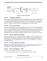
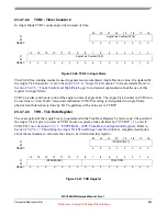
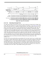
Figure 23-54. Time Base Synchronization
23.4.6.5
TCRCLK Digital Filter
The TCRCLK signal has an improved integrating digital filter with a 2-bit up-down counter. The counter
counts up to 3 when a high signal level is detected, or down to 0 when a low level is detected. The signal
state is updated to one when the counter stops at 3, or zero when the counter stops at 0. The field TCRCF
in register ETPUTBCR (see
Section 23.3.3.1, “ETPUTBCR - eTPU Time Base Configuration Register
determines whether the TCRCLK signal input (after a synchronizer) is filtered with the same filter clock
as the channel input signals (see
Section 23.4.5.6, “Enhanced Digital Filter - EDF
) or uses the system clock
divided by 2, and also whether the TCRCLK digital filter works in integrator mode or the same two sample
mode as the channel filters (see
The TCRCLK filter delay and prescaling determines the minimum detectable TCRCLK pulse widths and,
therefore, its maximum frequency, as shown in
Section 23.4.5.6.4, “Filter Clock Prescaler
and
. The TCRCLK signal delay from the module input to TCR1/TCR2 incrementing or detection
in the EAC logic is explained in
Section 23.6.1.2, “Input/Output Signal Delays
.
23.4.7
EAC - eTPU Angle Counter
23.4.7.1
General
The EAC logic contains a mechanism which follows the flywheel angle, based on the tooth rate. This
hardware works in combination with the TCRCLK signal, the TCR2 counter and Channel 0, 1 or 2
(depending on the ETPUTBCR field AM) to generate angle information on the TCR2 bus which is passed
to all the local engine channels. The EAC helps to implement a digital angle PLL (see
), which
eTPU SYSTEM
etpu_gtbe_out
etpu_gtbe_in
ETPUMCR[GTBE]
eTPU SYSTEM
etpu_gtbe_out
etpu_gtbe_in
MODULE X
gtbe_out
gtbe_in
SYNCHRONIZATION
LOGIC
SYNCHRONIZATION
BETWEEN eTPU TIME
BASES ONLY
SYNCHRONIZATION BETWEEN eTPU TIME
BASES AND OTHER MODULE TIME BASES
ETPUMCR[GTBE]


