


MPC563XM Reference Manual, Rev. 1
Freescale Semiconductor
1231
Preliminary—Subject to Change Without Notice
The content and usage of the
register depends on the transfer direction of
initiated frame. If the application initiates a TX frame transfer, i.e the TD bit is set to 1, the content and
usage shown in
LIN TX Register (LINTX) - TX Frame
applies. If the application initiates an RX frame,
i.e the TD bit is set to 0, the content and usage shown in
LIN TX Register (LINTX) - RX frame
The initiation and transmit of a TX frame is described in
Section 27.4.6.3, “LIN TX Frame generation
”.
The initiation and transmit of a RX frame is described in
Section 27.4.6.4, “LIN RX frame generation
The write access counter for this register is reset if at least one of the following events occurred
•
LIN Control Register 1 (LINCTRL1)
was set
•
SCI Status Register 2 (SCISR2)
was set
and
then cleared
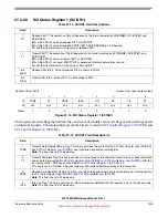
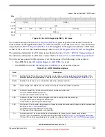
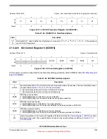
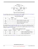
Access: User write (when TXRDY is set)
Byte
7
6
5
4
3
2
1
0
R
1st W
P[1:0]
ID[5:0]
2nd W
LEN
3rd W
CSM
CSE
CRC
TD
TO[11:8]
4th W
TO[7:0]
Reset
0
0
0
0
0
0
0
0
Figure 27-18. LIN TX Register (LINTX) - RX frame
Table 27-21. LINTX Field Descriptions
Field
Description
P[1:0]
Identifier Parity. This field provides the identifier parity which is used to create the protected identifier if the
automatic identifier parity generation is disabled, i.e the PRTY bit in
LIN Control Register 1 (LINCTRL1)
is 0.
ID[5:0]
Identifier. This field is used for the identifier field in the protected identifier.
LEN
Frame Length. This field defines the number of data bytes to be transmitted or received.
CSM
Checksum Model. This bit controls the checksum calculation model used.
0 Classic Checksum Model (LIN 1.3).
1 Enhanced Checksum Model (LIN 2.0).
CSE
Checksum Enable. This bit control the generation and checking of the checksum byte.
0 No generation and checking of checksum byte.
1 Generation and checking of checksum byte.
CRC
CRC Enable. This bit controls the generation of checking standard or enhanced LIN frames, which are described
in
Section 27.4.6.2, “LIN frame formats
0 Standard LIN frame generation and checking.
1 Enhanced LIN frame generation and checking.
TD
Transfer Direction. This bit control the transfer direction of the data, crc, and checksum byte fields.
0 Data, CRC, and Checksum byte fields received, described in
Section 27.4.6.4, “LIN RX frame generation
”.
1 Data, CRC, and Checksum byte fields transmitted, described in
Section 27.4.6.3, “LIN TX Frame generation
”.


