


Pulse-Width Modulation (PWM) Module
MCF52110 ColdFire® Integrated Microcontroller Reference Manual, Rev. 1
26-10
Freescale Semiconductor
Preliminary
(PWME
n
=0), the PWMCNT
n
register does not count. When a channel is enabled (PWME
n
=1), the
associated PWM counter starts at the count in the PWMCNT
n
register. For more detailed information on
the operation of the counters, refer to
Section 26.3.2.4, “PWM Timer Counters.”
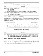
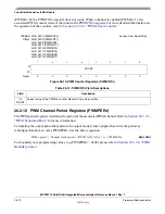
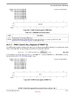
26.2.10 PWM Channel Period Registers (PWMPER
n
)
The PWM period registers determine the period of the associated PWM channel. Refer to
for more information.
Calculating the output period depends on the output mode (center-aligned has twice the period as
left-aligned mode) as well as PWMPER
n
. See the below equation:
Eqn. 26-3
For boundary case programming values (e.g. PWMPER
n
= 0x00), please refer to
.
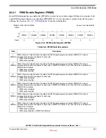
IPSBAR
Offset:
0x1B_000C (PWMCNT0)
0x1B_000D (PWMCNT1)
0x1B_000E (PWMCNT2)
0x1B_000F (PWMCNT3)
0x1B_0010 (PWMCNT4)
0x1B_0011 (PWMCNT5)
0x1B_0012 (PWMCNT6)
0x1B_0013 (PWMCNT7)
Access: User Read/Write
7
6
5
4
3
2
1
0
R
COUNT
W
Reset:
0
0
0
0
0
0
0
0
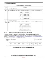
Figure 26-10. PWM Counter Registers (PWMCNT
n
)
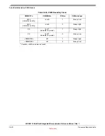
Table 26-10. PWMCNT
n
Field Descriptions
Field
Description
7–0
COUNT
Current value of the PWM up counter. Resets to zero when written.
PWM
n
period
Channel clock period
PWMCAE CAE
n
[
]
1
+
(
)
PWMPER
n
×
×
=


