


Hardware Description
Slave Board
DRM047 — Rev 0
Designer Reference Manual
MOTOROLA
Hardware Description
29
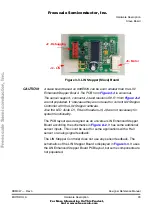
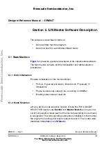
Figure 3-3. LIN Stepper (Slave) Board
CAUTION:
A slave board based on 908E625 can be even smaller than the LIN
Enhanced Stepper Board. The PCB from
is universal.
The sensor support - connector J4 and resistors R2, R1 from
are not populated. It ‘s because they are not used for current LIN Stepper
Controller with the LIN Stepper software.
Also the LED diode D1, R4 and headers J5, J6 are not necessary for
system functionality.
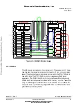
The PCB layout was designed as an universal LIN Enhanced Stepper
Board according the schematics in
. It has some additional
sensor inputs. This could be used for some applications with a Hall
sensor or analog signal feedback.
The LIN Stepper Controller does not use any sensor feedback. The
schematics of the LIN Stepper Board s displayed in
. It uses
the LIN Enhanced Stepper Board PCB layout, but some components are
not populated.
J3 - Motor
J2 - Debugging
J2 - LIN
F
re
e
sc
a
le
S
e
m
ic
o
n
d
u
c
to
r,
I
Freescale Semiconductor, Inc.
For More Information On This Product,
Go to: www.freescale.com
n
c
.
..


